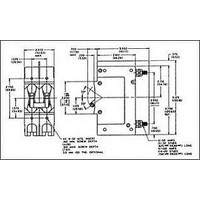
209-2-1-62-4-9-60 AIRPAX, 209-2-1-62-4-9-60 Datasheet - Page 16

209-2-1-62-4-9-60
Manufacturer Part Number
209-2-1-62-4-9-60
Description
CIRCUIT BREAKER, HYD-MAG, 2P, 240V, 60A
Manufacturer
AIRPAX
Series
209r
Datasheet
1.209-1-1-52-2-9-60.pdf
(20 pages)
Specifications of 209-2-1-62-4-9-60
Input Voltage Vac
240V
No. Of Poles
2
Current Rating
60A
Interrupting Capacity
5kA
Trip Time
18s
Voltage Rating Vdc
0V
Trip Time Max
18sec
Trip Time Min
2sec
Mounting Type
Panel
Rohs Compliant
Yes
Lead Free Status / RoHS Status
Lead free / RoHS Compliant
179
209/219/229/279 DECISION TABLES
How to Order
The ordering code for 209, E-Frame Circuit Breakers may be
determined by following the steps in the decision tables
shown here.
The coding given permits a self-assigning part number for
standard configurations. Factory part numbers are assigned
to units with mixed ratings, combinations of styles or con-
struction not listed in the Third Decision Table, etc. With
these, it is suggested that order entry be by description and/
or drawings, and a part number will be established.
Additionally, it is standard policy to establish a factory-
assigned part number whenever a descriptive drawing
exists to insure cross reference, traceability and manufac-
turing control.
When specifying a breaker for AC motor start or high inrush
applications, the peak amplitude and surge duration should
be specified for factory assistance in rating selection. 209
and 239 are UL listed circuit breakers under file no. E53739
per UL 489.
279 is a UL listed under file no. E192808 per UL 489A.
219 is a UL recognized “Manual Motor Controller” under file
no. E41607 per UL 508.
229 is a UL recognized supplementary protector under file
no. E66410 per UL 1077.
For example, the following is the code for a single pole
breaker with series trip, 50/60Hz, medium inertial delay,
120/240Vac maximum voltage ratings, solderless connector
with mounting foot added to the line side of the breaker to
facilitate back panel mounting and a current rating of 10.0
amperes.
To determine the ordering number of your particular 209 unit,
simply follow the steps shown. you may use this number to
place an order or as a reference for further questions you may
have.
Notes:
A 6-32 inserts for front mounting are provided on all units. M3 ISO metric mounting
B The auxiliary switch is located on the right-hand pole (viewed from terminal end)
inserts are available and are specified by adding -A at the end of the ordering
code above.
unless specified otherwise. Auxiliary switches are available on all front or back
panel mounts (series construction only). If more than one auxiliary switch is speci-
fied use “2R” through “6R” as required.
209/219/229/249/279 Series - Decision Tables
C Line terminals are 10-32 screws for bus connection to 100 amperes. Load termi-
D An anti-flashover barrier is supplied between poles on all multi-pole versions
E The standard current values for 100% of rated current are those listed in the
nals are 10-32 screws to 50 amperes and solderless connectors from 50 to 100
amperes.
with 10-32 stud and 1/4-20 stud terminals per UL requirement.
Seventh Decision Table. Non-listed values can be readily supplied, in general
without delayed delivery. Please contact an Airpax office or sales representative.
http://airpax.sensata.com/


