OP140B OPTEK TECHNOLOGY, OP140B Datasheet
OP140B
Manufacturer Part Number
OP140B
Description
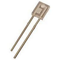
IR EMITTER 935NM 0.79MM SIDE LOOKING THD
Manufacturer
OPTEK TECHNOLOGY
Datasheet
1.OP140A.pdf
(2 pages)
Specifications of OP140B
Peak Wavelength
935nm
Forward Current If(av)
20mA
Rise Time
1µs
Fall Time Tf
500ns
Supply Voltage Range
1.6V
Operating Temperature Range
-40°C To +100°C
Viewing Angle
40°
Lead Free Status / RoHS Status
Lead free / RoHS Compliant


Prod uct Bul le tin OP140A
May 1996
GaAs Plas tic In fra red Emit ting Di odes
Types OP140A, OP140B, OP140C, OP140D
Fea tures
De scrip tion
The OP140 series devices are 935nm
high intensity gallium arsenide infrared
emitting diodes molded in IR
transmissive plastic side-looking
packages. The side looking packages
are for use in PC board mounted slotted
switches or as an easy mount PC board
interrupter.
Re places
OP140SL series
Wide irradiance pattern
Selected to specific on-line intensity
ranges
Low cost, miniature plastic side-
looking package
Mechanically and spectrally matched
to the OP550 series of
phototransistors and the OP560 series
of photodarlingtons
Ab so lute Maxi mum Rat ings (T
Re verse Volt age . . . . . . . . . . . . . . . . . . . . . . . . . . . . . . . . . . . . . . . . . . . . . . . . . 2.0 V
Con tinu ous For ward Cur rent . . . . . . . . . . . . . . . . . . . . . . . . . . . . . . . . . . . . . . . 50 mA
Peak For ward Cur rent (1 s pulse width, 300 pps) . . . . . . . . . . . . . . . . . . . . . . . 3.0 A
Stor age and Op er at ing Tem pera ture Range . . . . . . . . . . . . . . . . . . -40
Lead Sol der ing Tem pera ture [1/16 inch (1.6 mm) from case for 5 sec. with sol der ing
iron] . . . . . . . . . . . . . . . . . . . . . . . . . . . . . . . . . . . . . . . . . . . . . . . . . . . . . . . . 260
Power Dis si pa tion . . . . . . . . . . . . . . . . . . . . . . . . . . . . . . . . . . . . . . . . . . . . 100 mW
Notes:
(1) RMA flux is recommended. Duration can be extended to 10 sec. max. when flow soldering.
(2) Derate linearly 1.33 mW/
(3) E
A max. of 20 grams force may be applied to the leads when soldering.
0.180" (4.57 mm) in diameter perpendicular to and centered on the mechanical axis of the
lens and 0.653" (16.6 mm) from the lens tip. E
measured area.
e(APT)
is a measurement of the average apertured radiant incidence upon a sensing area
2-10
o
C above 25
A
o
= 25
C.
o
e(APT)
C un less oth er wise noted)
is not necessarily uniform within the
o
C to +100
o
C
o
(1)
(2)
C
Related parts for OP140B
Image
Part Number
Description
Manufacturer
Datasheet
Request
R

Part Number:
Description:
REFLECTIVE PHOTOTRANSISTOR
Manufacturer:
OPTEK TECHNOLOGY
Datasheet:

Part Number:
Description:
IR EMITTER, 890NM, T-1 3/4, THROUGH HOLE
Manufacturer:
OPTEK TECHNOLOGY
Datasheet:
Part Number:
Description:
IR EMITTER, 890NM, T-1 3/4, THROUGH HOLE
Manufacturer:
OPTEK TECHNOLOGY
Datasheet:
Part Number:
Description:
IR EMITTER, 890NM, T-1 3/4, THROUGH HOLE
Manufacturer:
OPTEK TECHNOLOGY
Datasheet:
Part Number:
Description:
IR EMITTER, 890NM, 4.65MM, TO-18-2, THD
Manufacturer:
OPTEK TECHNOLOGY
Datasheet:
Part Number:
Description:
IR EMITTER, 890NM, 4.83MM, TO-18-2, THD
Manufacturer:
OPTEK TECHNOLOGY
Datasheet:

Part Number:
Description:
IR EMITTER, 890NM, 1.9MM, SMD
Manufacturer:
OPTEK TECHNOLOGY
Datasheet:

Part Number:
Description:
IR EMITTER, 890NM, 1.9MM, SMD
Manufacturer:
OPTEK TECHNOLOGY
Datasheet:
Part Number:
Description:
DIODE, LASER, 850NM, 1.5mW
Manufacturer:
OPTEK TECHNOLOGY
Datasheet:

Part Number:
Description:
OBJECT SENSOR, DARLINGTON
Manufacturer:
OPTEK TECHNOLOGY
Datasheet:

Part Number:
Description:
TRANSISTOR PNP GP HERMETIC SMD
Manufacturer:
TT Electronics/Optek Technology
Datasheet:
Part Number:
Description:
TRANSISTOR PNP GP HERMETIC SMD
Manufacturer:
TT Electronics/Optek Technology
Datasheet:
Part Number:
Description:
TRANSISTOR NPN GP HERMETIC SMD
Manufacturer:
TT Electronics/Optek Technology
Datasheet:

Part Number:
Description:
LED IR 880NM FLAT LENS 0805 SMD
Manufacturer:
TT Electronics/Optek Technology
Datasheet:
Part Number:
Description:
NPN-Output Dc-Input Optocoupler,1-CHANNEL,1kV ISOLATION,Can-8.1
Manufacturer:
OPTEK TECHNOLOGY
Datasheet:
OP140B Summary of contents
Page 1
... Prod uct Bul le tin OP140A May 1996 GaAs Plas tic In fra red Emit ting Di odes Types OP140A, OP140B, OP140C, OP140D Fea tures Wide irradiance pattern Selected to specific on-line intensity ranges Low cost, miniature plastic side- looking package Mechanically and spectrally matched ...
Page 2
... Types OP140A, OP140B, OP140C, OP140D Elec tri cal Char ac ter is tics ( SYM BOL PA RAME TER Apertured Radiant Incidence E e(APT) V Forward Voltage F I Reverse Current R Wavelength at Peak Emission p B Spectral Bandwidth Between Half Power Points Spectral Shift with Temperature / P T Emission Angle at Half Power Points ...