OPI7010 OPTEK TECHNOLOGY, OPI7010 Datasheet
OPI7010
Specifications of OPI7010


Related parts for OPI7010


OPI7010 Summary of contents
Page 1
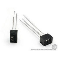
... UL registered File No. E8730 Description: Each OPI7002 and OPI7010 consists of an infrared emitting diode coupled to a NPN silicon phototransistor. The LED and sensor are encased in a black, low-cost plastic housing. Pin spacing is compatible with standard dual-in- line packages. Each OPI7320 and OPI7340 consists of an infrared emitting diode coupled to a NPN silicon photodarlington. The LED and sensor are encased in a high dielectric plastic housing ...
Page 2
... Forward DC Current Peak Forward current (1 µs pulse width, 300 pps) Reverse Voltage (3) Power Dissipation Output Phototransistor Collector-Emitter Voltage OPI7002, OPI7010, OPI7002RCE, OPI7010RCE OPI7320, OPI7340, OPI7320RCE, OPI7340RCE Emitter-Collector Voltage (3) Power Dissipation Notes: (1) Measured with input leads and output leads shorted. (2) RMA flux is recommended. Duration can be extended to 10 seconds maximum when flow soldering. ...
Page 3
... Input Diode (See OP140 or OP240 for additional information—for reference only) V Forward Voltage F I Reverse Current R Output Phototransistor (OPI7002, OPI7010) (See OP550 for additional information—for reference only) Output Photodarlington (OPI7320, OPI7340) (See OP560 for additional information—for reference only) Collector-Emitter Breakdown Voltage V OPI7002/RCE, OPI7010/RCE (BR)CEO OPI7320/RCE, OPI7340/RCE ...