HFBR-0539Z Avago Technologies US Inc., HFBR-0539Z Datasheet - Page 14
HFBR-0539Z
Manufacturer Part Number
HFBR-0539Z
Description
DC-12MBd Profibus 650nm Eval Kit
Manufacturer
Avago Technologies US Inc.
Specifications of HFBR-0539Z
Main Purpose
Interface, Fiber Optics
Embedded
No
Utilized Ic / Part
HFBR-1515BZ, HFBR-2515BZ
Primary Attributes
DC ~ 12MBd TTL
Secondary Attributes
SMA Connectors
Operating Voltage
5 V
Description/function
Versatile Fiber Optic Evaluation Kit
Maximum Operating Temperature
+ 85 C
Minimum Operating Temperature
- 40 C
Operating Current
6.2 mA
Leaded Process Compatible
Yes
Rohs Compliant
Yes
Peak Reflow Compatible (260 C)
Yes
Lead Free Status / RoHS Status
Lead free / RoHS Compliant
For Use With/related Products
HFBR-1515BZ, HFBR-2515BZ
Lead Free Status / RoHS Status
Lead free / RoHS Compliant
Other names
516-2252


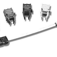
HFBR-25X2Z/25X4Z Receivers
DO NOT CONNECT
DO NOT CONNECT
Absolute Maximum Ratings
Notes:
1. 1.6 mm below seating plane.
2. It is essential that a bypass capacitor 0.1 μF be connected from pin 2 to pin 3 of the receiver. Total lead length between both ends of the
Receiver Electrical/Optical Characteristics
Notes:
1. Measured at the end of the fiber optic cable with large area detector.
2. Pulsed LED operation at I
3. The LED drive circuit of Figure 11 is required for 1 MBd operation of the HFBR-25X2Z/25X4Z.
4. Optical flux, P (dBm) = 10 Log [P(μW)/1000 μW].
5. R
14
Parameter
Storage Temperature
Operating Temperature
Lead Soldering Cycle
Supply Voltage
Output Collector Current
Output Collector Power Dissipation
Output Voltage
Pull-up Voltage
Fan Out (TTL)
Parameter
Receiver
Optical Input
Power Level
Logic 0
Optical Input Power
Level Logic 1
High Level Output Current
Low Level Output Voltage
High Level Supply Current
Low Level Supply Current
Effective Diameter
Numerical Aperture
Internal Pull-up Resistor
capacitor and the pins should not exceed 20 mm.
width distortion of the receiver output signal.
L
is open.
5
8
HFBR-2522Z
HFBR-2524Z
F
> 80 mA will cause increased link t
1000 Ω
4
3
2
1
Temp.
Time
R
V
GROUND
V
Symbol
CC
O
L
P
P
I
I
V
I
NA
CCH
CCL
R(H)
OH
R
R(L)
D
OL
L
0°C to 70°C, 4.75 V ≤V
Min.
680
–24
–20
Symbol
PLH
I
P
V
OAV
V
V
T
T
N
OD
CC
propagation delay time. This extended t
A
S
O
P
1000
Typ.
0.4
3.5
6.2
0.5
5
1
Note: Pins 5 and 8 are for mounting and retaining purposes only. Do not
electrically connect these pins.
CC
Pin #
1
2
3
4
5
8
≤5.25 V unless otherwise specified.
1700
Max.
250
-43
0.5
6.3
Min.
–0.5
–0.5
10
–40
–40
–5
Units
dBm
dBm
mm
mA
mA
μA
Ω
V
Function
V
Ground
V
R
Do not connect
Do not connect
O
CC
Max.
L
+85
+85
260
V
10
25
40
18
7
5
CC
V
I
V
I
V
I
P
V
P
V
P
OL
OH
OL
OL
OH
CC
R
R
R
O
CC
= P
= 0
= -12.5 dBm
= 18 V, P
= 8 mA
= 8 mA
= ≤250 μA
= 5.25 V,
= 0 V
Conditions
= 5.25 V,
= 5.25 V
PLH
R(L)MIN
time contributes to increased pulse
Units
mW
sec
mA
°C
°C
°C
V
V
V
R
= 0
Reference
Note 1
Note 2
Notes 1, 2, 3
Note 4
Note 5
Note 5
Note 5
Note 5
Ref.
Related parts for HFBR-0539Z
Image
Part Number
Description
Manufacturer
Datasheet
Request
R

Part Number:
Description:
Fiber Optic Transmitters, Receivers, Transceivers 1300nm 155MBd 16-pin DIP ST Rx
Manufacturer:
Avago Technologies US Inc.

Part Number:
Description:
FIBER OPTIC TX 125 MBD 650N
Manufacturer:
Avago Technologies US Inc.
Datasheet:

Part Number:
Description:
Fiber Optic Evaluation Kit
Manufacturer:
Avago Technologies US Inc.
Datasheet:

Part Number:
Description:
RECEIVER FIBER OPTIC ST 266MBD
Manufacturer:
Avago Technologies US Inc.
Datasheet:

Part Number:
Description:
RCVR OPT HI SPEED VERS LINK HORZ
Manufacturer:
Avago Technologies US Inc.
Datasheet:

Part Number:
Description:
RCVR OPT HI SPEED VERS LINK VERT
Manufacturer:
Avago Technologies US Inc.
Datasheet:

Part Number:
Description:
TXRX OPTICAL 850NM VCSEL MT-RJ
Manufacturer:
Avago Technologies US Inc.
Datasheet:

Part Number:
Description:
TXRX MM SFP LC CONN BAIL DELATCH
Manufacturer:
Avago Technologies US Inc.
Datasheet:

Part Number:
Description:
TXRX MMF SFP GBE/FC BAIL DELATCH
Manufacturer:
Avago Technologies US Inc.
Datasheet:

Part Number:
Description:
XMITTER FIBER OPTIC 266MBD ST
Manufacturer:
Avago Technologies US Inc.
Datasheet:

Part Number:
Description:
OPTOCOUPLER GATE DRV 2A 16-SOIC
Manufacturer:
Avago Technologies US Inc.
Datasheet:
Part Number:
Description:
OPTOCOUPLER 2CH 2.5A 16-SOIC
Manufacturer:
Avago Technologies US Inc.
Datasheet:

Part Number:
Description:
OPTOCOUPLER GATE DRV 0.4A 16SOIC
Manufacturer:
Avago Technologies US Inc.
Datasheet:

Part Number:
Description:
OPTOCOUPLER 2.0A 250KHZ 8-DIP
Manufacturer:
Avago Technologies US Inc.
Datasheet:

Part Number:
Description:
OPTOCOUPLER 2.0A 250KHZ GW 8-SMD
Manufacturer:
Avago Technologies US Inc.
Datasheet: