FS2003(UN) Equinox Technologies, FS2003(UN) Datasheet
FS2003(UN)
Specifications of FS2003(UN)


Related parts for FS2003(UN)


FS2003(UN) Summary of contents
Page 1
...
Page 2
Contents Copyright Information ............................................................................................................iii Equinox Warranty Information ..............................................................................................iv Electromagnetic Compatibility (EMC) Compliance.............................................................vi Technical Support..................................................................................................................vii Product Documentation .......................................................................................................viii 1.0 Programmer Overview / Specifications...........................................................................1 1.1 System Contents ............................................................................................................1 1.2 Hardware Overview (external layout) .............................................................................2 1.3 Hardware Overview (internal layout) ..............................................................................3 1.4 Programmer ...
Page 3
Programmer Operating Modes .....................................................................................29 3.5 Development Mode (EDS) ............................................................................................30 3.5.1 Overview...............................................................................................................30 3.5.2 Launching EDS (Development Mode)..................................................................30 3.6 Standalone Keypad Mode.............................................................................................32 3.6.1 Overview...............................................................................................................32 3.6.2 Push Button Functions .........................................................................................34 3.6.3 Standalone Keypad Operation – step-by-step guide ...........................................35 3.6.4 Standalone Keypad Operation ...
Page 4
... The purchaser may make one copy of the software for backup purposes. No part of this manual may be reproduced or transmitted in any form or by any means, electronic, mechanical, including photocopying, recording, or information retrieval systems, for any purpose other than for the purchaser’s personal use, without written permission. © 2000 Copyright Equinox Technologies UK Limited. All rights reserved Atmel ...
Page 5
... Equinox Warranty Information This product is guaranteed by Equinox Technologies UK Limited for a period of 12 months (1 year) after the date of purchase against defects due to faulty workmanship or materials. One guarantee covers both parts and labour. Service under the guarantee is only provided upon presentation of reasonable evidence that the date of the claim is within the guarantee period (e.g. completed registration/guarantee card or a purchase receipt) ...
Page 6
... Equinox Technologies UK Ltd. cannot be held responsible for any programming problems which are ‘out of our control’. This type of problem is usually listed in the ‘Errata Sheet’ for the particular device being programmed and is available from the silicon vendor. Information contained in this manual is for guidance purposes only and is subject to change. E& ...
Page 7
Electromagnetic Compatibility (EMC) Compliance The ‘FS2003 Programmer’ Approved Product designed for use in an ESD controlled environment i.e. development or production. This means, therefore, that the user must ensure that there is no possibility of ...
Page 8
... If you have a technical support problem, please consult the following list for help: ► Manual ► On-line help Press <F1> for help at any time when running EQTools or ISP-PRO. The help system is context-sensitive. Simply press <F1> on any error message and the Possible causes of the error should be listed. This help system is updated on a regular basis ...
Page 9
... Error Message Descriptions This document lists all the possible error messages which can be generated by the EQTools / ISP-PRO applications. This document can be found on the CD-ROM which comes with the programmer. ASCII Text Communications Protocol This protocol can be used to control the programmer from an external controller via RS-232. Please refer to Application Note – ...
Page 10
Remote Application Control – Application Note Describes how to control the programmer using a custom Remote Application written in e.g. Visual Basic, C++, C Builder, Delphi etc. Downloading up-to-date documentation and software: In line with our policy of continuous improvement, ...
Page 11
...
Page 12
... Female to 9-way Male Serial Cable • 25-way Female to 9-way Male Serial Adaptor • 10 way ISP Cable • 6 way ISP Cable Miscellaneous • Jumper Link Software (Supplied on an Equinox CD-ROM) • EQTools (Project Management Utility for Equinox Production ISP Programmers) Documentation • FS2003 - User Guide 1 ...
Page 13
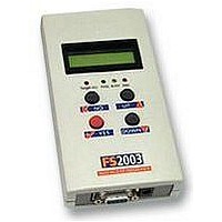
Hardware Overview (external layout) 2 Top Panel ISP Cable Slot ISP cable plugs into relevant ISP Header internally and then exits the case through this slot. Front Panel <Target Vcc> LED - Indicates when ‘Target Vcc’ ...
Page 14
Hardware Overview (internal layout) FS2003 ISP Programmer - User Guide V1.01 – 4th February 2004 Hardware 1. Atmel 6-way ISP (SPI) Header (J3) 2. Equinox 10-way ISP (SPI / UART) Header (J6) 3. Atmel 10-way ISP (SPI) Header (J7) ...
Page 15
Programmer Specifications Overview The table below details the hardware specifications for the programmer. Please refer to the stated section for further information about any specific parameter. # Paramater Description / comment 1 Target Device See Device Support List Support ...
Page 16
... PC Control Software The programmer can be controlled using: As standard: • Optional chargeable upgrades: • • 10 EQTools / ISP-PRO PC running Windows 2000 / ME / NT4 / XP PC requirements 11 Power Supply There are 3 possible modes for powering the Programmer / Options Target System: • • • 12 Voltage range • ...
Page 17
... This clock frequency could be used for the following purposes: • • Please refer to the ‘EQTools – Getting Started Guide’ for full details of setting up the SCK2 oscillator. 22 Target Run The programmer is capable of automatically running firmware which has been programmed into a Target Device and waiting until the MISO pin is asserted by the Target Device ...
Page 18
Device Support 1.5.1 Devices supported by the programmer The programmer supports the following devices: # Manufacturer Family 1 Atmel AT89S 2 Atmel AT90S (AVR) 3 Atmel ATmega (AVR) 4 Atmel ATmega (AVR) 5 Atmel ATtiny (AVR) LV SPI 6 ...
Page 19
Programming Interface to Target Device The programmer supports the following programming interfaces to the Target Device: # Programming Family Interface 1 LV SPI AT89S AT90S ATmega ATtiny 2 HV SPI (+12V ATtiny Vpp) 3 UART Boot T89C51Rx2 Loader P89X51Rx2 ...
Page 20
DC Power Input Connector (CON1 possible to power the programmer from an external power supply by plugging the DC Power Cable supplied with the programmer into CON1. This connector is a 2.5mm jack socket. Fig. 1.6.1 CON1 ...
Page 21
J5 – RS-232 Communications Port & Serial Cables 1.8.1 Connecting the programmer to the PC COM port The programmer communicates with a PC via the RS-232 Communications Port (J5). A suitable 9- way to 9-way serial cable is supplied ...
Page 22
Serial Cable Pin-outs Fig. 1.8.3.1 Pin-out RS-232 Communications Port Pin No. RS232 pin Description 1 DCD Not Connected 2 RXD Receive 3 TXD Transmit 4 DTR Not Connected 5 0 Volt 0V 6 DSR Not Connected ...
Page 23
FS2003 ISP Programmer - User Guide V1.01 – 4th February 2004 ...
Page 24
Hardware Installation 2.1 Overview This section details how to set up FS2000A programmer hardware including Power Supply, Earthing Requirements, PC Serial Port Connection and ISP Header Selection. ESD Precautions • • • • • FS2003 ISP Programmer - User ...
Page 25
Removing the programmer cover a Remove programmer from all packaging and place display-side down on a flat surface b Remove all four screws from the back of the programmer (if fitted) c Remove programmer cover to reveal internal electronics ...
Page 26
Powering the Programmer / Target System 2.3.1 Select the required method of powering the Programmer / Target System The programmer supports the following power supply methods: Sect Power Supply method 2.3.2 Powering the Target System at +5.0V from the ...
Page 27
Fig. 2.3.1 FS2003 – Power Supply Overview Schematic 16 FS2003 ISP Programmer - User Guide V1.01 – 4th February 2004 ...
Page 28
Powering the Target System at +5.0V from the programmer (external mains power supply adaptor) 2.3.3. Powering the Target System at +5.0V from the programmer (external bench power supply) FS2003 ISP Programmer - User Guide V1.01 – 4th February 2004 ...
Page 29
Powering the programmer from the Target System at 3.0 – 5.0V 2.3.5 Programmer and Target System are Independently powered 18 • The Target System can supply power to the programmer as long as the Target Voltage is 3.0 – ...
Page 30
Selecting the correct ISP (In System Programming) Header a Select the required ISP Header and then plug the ISP Cable into this Header. Please refer to section 4 of this manual for full details of all the available headers. ...
Page 31
Connecting the programmer to the PC Serial (COM) Port The programmer communicates with a PC via the RS-232 Communications Port (J5) The programmer is supplied with the following PC Serial Cables / Adaptors: • 9-way D (Female) to 9-way ...
Page 32
Earthing requirements 2.6.1 Overview When setting up the programmer to In-System Program (ISP) a device on a Target System, extreme care must be taken to ensure that the 0V of the PC, programmer, Target System and any external devices ...
Page 33
Earthing recommendations To avoid catastrophic damage to PC, programmer or target system: • Ensure that both your target system and PC are connected to a common earth point • Make sure that all interconnections are made before applying power ...
Page 34
... Standalone Mode. • not possible to check the programmer information until a valid project is uploaded. Please upload a valid project to the programmer using EQTools and then try again. • The programmer display now shows the programmer type and the firmware version. e.g. 2.37. • ...
Page 35
Re-assembling the programmer a Re-fit lid to programmer b Re-fit the four screws in the back of the case c Ensure that the PC, programmer and Target System power is switched OFF. Please note: • The FAIL LED will ...
Page 36
... Memory Store’ is empty so the programmer cannot be used in Standalone Mode. • Please upload a valid project to the programmer using EQTools and then try again. • The FAIL LED will flash when you initially power up the programmer. • To clear the FAIL LED condition, use the < ...
Page 37
... Certain options such as compiling and running of ‘Programming Scripts’ must be purchased from Equinox as a ‘License upgrade. The table below details the various EQTools components and whether they are enabled as standard. Fig. 3.1 Software / Control Options for the FS2003 Programmer ...
Page 38
... Programmer Control Mechanisms The programmer can be controlled from EQTools, from a Remote System and via the Equinox ISP- PRO software. As overview of the various control mechanisms is given below. Standalone Operation(Keypad) This indicates that the programmer can be operated without being connected other control system ...
Page 39
... EQTools versions are quoted as e.g. EQTools V2.1.0 Build 466 The filename for this version would be ‘eqtools210_466.exe’ For further information, please locate the ‘EQTools – Getting Started Guide’ PDF document either on the CD-ROM supplied with the programmer or from the Equinox Web Site. Refer to Section 2 of the guide for detailed EQTools installation instructions ...
Page 40
... Remote System which features an RS-232 serial port and which can operate at a fixed baud rate of 38,400 this mode, the programmer is controlled from a ‘Programming Script’ running within either the EQTools or ISP-PRO applications on a PC. Refer to section 3.5 3.6 3.7 3 ...
Page 41
... Development Mode (EDS) 3.5.1 Overview In ‘Development Mode’, the programmer is controlled from the EQTools - Equinox Development Suite running on a PC. The Development utility is called Equinox Development Suite or EDS for short. In this mode it is NOT necessary to upload the ‘Programming Project’ to the programmer as the EDS utility co-ordinates all programming operations ...
Page 42
... Click the <Write> button to write the data in the Buffer Window to the Target Device For further instructions about how to use the EDS utility, please refer to the ‘EQTools – Getting Started Guide’ which can be found on the CD-ROM supplied with the programmer. ...
Page 43
Standalone Keypad Mode 3.6.1 Overview In ‘Standalone Mode’, the FS2003 is controlled via the push buttons on the front panel of the programmer. The programmer LCD and the LED Status Indicators are used to display the current status of ...
Page 44
... Follow the instructions to program the Target Device in Standalone Mode FS2003 ISP Programmer - User Guide V1.01 – 4th February 2004 Observation / comment Programmer Target Vcc LED illuminates See EQTools Manual – Project Upload Wizard for full instructions. Programmer is no longer controlled from PC 33 ...
Page 45
Push Button Functions Button 34 The FS2003 programmer features a four button keypad which is used to control the programmer when it is operating in ‘Standalone Mode’. The function of these buttons is described below. Function of button The ...
Page 46
... LCD not required while operating in Standalone Mode. 1. Ensure that you have already uploaded a valid ‘Project Collection’ to the programmer • Use the EQTools – Upload Wizard to upload your ‘Project Collection’. 2. Select the ‘Programming Project’ which you wish to execute: • ...
Page 47
Wait for the programmer to CRC check the Programming Project • The programmer performs a full CRC validation check of the entire Programming Project stored in the programmer ‘FLASH Memory Store’. • If the check is OK, the programmer ...
Page 48
Programming Project – FAIL If the Programming Project fails for some reason: • The <FAIL> LED will FLASH • The programmer will automatically remove power from the Target System (if the programmer is controlling power) • The LCD will ...
Page 49
Standalone Keypad Operation – Flowchart The flowchart below details how a ‘Programming Project’ is selected in ‘Standalone Mode’. Select Project Project1 T <UP> <DOWN> key key T Select Project Project2 T <UP> <DOWN> key key T Select Project Projectn ...
Page 50
Programmer Status LED’s The current status of the programmer is displayed on the programmer Status LED’s as detailed in the table below. Fig. 2.6.5 Programmer Status LED’s – state descriptions Status LED State Display WAITING BUSY FAIL PASS Status ...
Page 51
... The protocol does not support writing / reading of individual bytes or blocks of data to / from a Target Device. 3. The protocol does not support uploading of ‘Programming Projects’ to the programmer. This must be performed using the EQTools – Project Upload Wizard. 4. Only very limited diagnostics are available using this protocol ie. FAIL + Error Number. 40 ...
Page 52
Further Information A full description of this protocol can be found in the Application Note ‘AN110 - ASCII Text Control (ATC) Protocol for Remote Control of Equinox Programmers’. FS2003 ISP Programmer - User Guide V1.01 – 4th February 2004 ...
Page 53
Script Mode ‘Script Mode’ is designed for production users who require logging of all programmer operations to a database. This mode utilises the Equinox ISP-PRO software which allows execution of Programming Scripts possible to write scripts to ...
Page 54
ISP Header Selection 4.1 Overview The FS2003 programmer caters for many different connection methods to a Target System by featuring FOUR possible ISP Header connectors. Each header provides the necessary signals to program the Target Device plus Vcc (power) ...
Page 55
ISP Header Selection Chart (by header) The FOUR ISP Headers featured on the FS2003 are detailed in the table below. Please refer to the section indicated in the ‘refer to section’ column for specific details of each header. # ...
Page 56
J8 Atmel 10-way JTAG Header Device support: Atmel ATmega32/128 + any new devices with JTAG port FS2003 ISP Programmer - User Guide V1.01 – 4th February 2004 4.9 45 ...
Page 57
ISP Header Selection Chart (by Device) The table below details which header to choose for a specified device or device family. The information contained in this manual does NOT show the actual connections to the Target Microcontroller. Please refer ...
Page 58
J3 - Atmel 6-way ISP Header (SPI Interface) This connection method is suitable for interfacing the programmer to a Target System which features the following: • Atmel 6-way IDC ISP Header • An Atmel device which features the 3-wire ...
Page 59
... This pin controls the Target Device RESET pin. It will driven HIGH/LOW according to the device type and settings in the ‘Pre-program State Machine’ tab in the Eqtools project. GROUND Ground Connection Common ground connection between PROGRAMMER and Target System. FS2003 ISP Programmer - User Guide V1.01 – 4th February 2004 ...
Page 60
... Machine> tab. XTAL1 SCK2 Clock Output (*Optional*) This output signal can be used to Only connect this pin if supply an external clock signal you are using the (SCK2) to the target microcontroller. SCK2 Clock Output to This function must be enabled in the clock the Target EQTools <Pre-programming State 49 ...
Page 61
... Target RESET control pin This pin controls the Target Device RESET pin. It will driven HIGH/LOW according to the device type and settings in the <Pre-program State Machine> tab in the Eqtools project. Warning! During ‘High Voltage Serial Programming’ of the Atmel ATtiny11/12/15 microcontrollers, a +12V Vpp voltage is generated by the programmer on this pin. FS2003 ISP Programmer - User Guide V1.01 – ...
Page 62
... Spare Programmer I/O pin This pin is currently a I/O spare pin which is not used during SPI programming. In order to use this pin, the pin state must be setup in the EQTools <Pre-programming State Machine> tab. XTAL1 SCK2 Clock Output This output pin is used to supply an external clock signal (SCK2) to the target microcontroller ...
Page 63
N PROG_SII O 7 PROG_GND P 8 PROG_SDO I 9 PROG_GND P 10 PROG_RESET/VPP O Key O - Output from programmer to Target Device I - Input to programmer from Target Device P - Passive eg. GROUND ...
Page 64
J6(c) - Equinox 10-way Header (UART Boot Loader) This connection method is suitable for interfacing the FS2003 programmer to a Target System which features the following: • Equinox 10-way IDC ISP Header • An Atmel Wireless T89C51Rx2 / CC01 ...
Page 65
... Target RESET control pin This pin controls the Target Device RESET pin. It will driven HIGH/LOW according to the device type and settings in the ‘Pre- program State Machine’ tab in the Eqtools project. Warning! During ‘High Voltage Serial Programming’ of the Atmel ATtiny11/12/15 microcontrollers, a +12V Vpp voltage is generated by the programmer on this pin ...
Page 66
J7 - Atmel 10-way Header (SPI Interface) This connection method is suitable for interfacing the programmer to a Target System which features the following: • Atmel 10-way IDC ISP Header • An Atmel device which features the 3-wire SPI ...
Page 67
... I - Input to programmer from Target Device P - Passive eg. GROUND and power rails N/C - Not connected 56 according to the device type and settings in the ‘Pre-program State Machine’ tab in the Eqtools project. GROUND Ground Connection Common ground connection between the programmer and Target System. SCK SPI Serial Clock Output This is the SPI clock output signal ...
Page 68
J8 - Atmel 10-way JTAG Header (JTAG Interface) This connection method is suitable for interfacing the programmer to a Target System which features the following: • An Atmel device which features a JTAG ISP port e.g. ATmega128 / 323 ...
Page 69
PROG_VCC PROG_TDI O 10 PROG_GND P Key O - Output from programmer to Target Device I - Input to programmer from Target Device P - Passive eg. GROUND and power rails N/C - Not ...
Page 70
ISP Cable considerations The programmer is supplied with a single 10-way ISP Cable as standard. This cable is terminated with a 10-way IDC 0.1” female polarised plug at each end. The cable is wired as a so-called ‘straigh- through’ ...