Q2686H DK WAVECOM, Q2686H DK Datasheet - Page 49
Q2686H DK
Manufacturer Part Number
Q2686H DK
Description
KIT. DEV, Q2686H, GSM/GPRS
Manufacturer
WAVECOM
Datasheet
1.Q2686H_DK.pdf
(66 pages)
Specifications of Q2686H DK
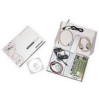
Kit Contents
Development Kit Q26 Board, Wireless CPU Soldered, SMA/FME Antenna, Adapter, RS232/USB Cable, CDROM
Development Tool Type
Development Kit
Kit Contents Descriptive
2x Q2686H Modules, 1x
Lead Free Status / RoHS Status
Lead free / RoHS Compliant


20 Measures of Current
To measure the current consumed by the Wireless CPU, use the configuration as
shown in Figure 20:
Do not solder the "special solder", J103.
On UART1:
- Remove R408.
- Place R406=0Ω (like R408).
On UART2:
- Remove R502 and R505.
- Place R506=0Ω (like R502).
- The UART2 link is not used, therefore J501, J502, J503, and J504 must be open
(by removing the solder).
- The switch UART2 must be switched to "GPIO1" position.
On BAT-TEMP:
- Remove R100.
- Plug an external power supply like VCC-EXT on "VBAT"(+), and (GND ) on "GND"(-).
This power supply may be set to 4 volts. Thus, peripherals may be used.
On USB:
The USB link is not used, therefore J801, J802, and J803 must be open (by removing
the solder).
With this configuration, the consumption current from VBATT is ONLY that of the
Wireless CPU plugged in. For further information refer to document.[3] or [6].
Note:
Before doing any modification, ensure that the Development Kit is disconnected from
the power supply during the work. Use pewter and a soldering iron (refer to WS80
from Weller or similar) to solder.
This document is the sole and exclusive property of Wavecom. Not to be distributed or divulged without
prior written agreement.
WM_BBD_Q26_UGD_001-004
©Confidential
Development Kit Q2686 and Q2687
Measures of Current
September 11, 2006
Page: 48/ 64
Related parts for Q2686H DK
Image
Part Number
Description
Manufacturer
Datasheet
Request
R

Part Number:
Description:
MODULE, GSM/GPRS, QUAD BAND
Manufacturer:
WAVECOM
Datasheet:
