B51-328-3188220 ITT SEALECTRO, B51-328-3188220 Datasheet - Page 54
B51-328-3188220
Manufacturer Part Number
B51-328-3188220
Description
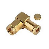
RF/COAXIAL, SMB PLUG, R/A, 50OHM, CRIMP
Manufacturer
ITT SEALECTRO
Datasheet
1.B50-051-0000220.pdf
(64 pages)
Specifications of B51-328-3188220
Body Style
Right Angle Plug
Coaxial Termination
Crimp
Rg Cable Type
RG-174, 316
Contact Material
Beryllium Copper
Contact Plating
Gold
Connector Type
SMB Coaxial
Impedance
50ohm
Lead Free Status / RoHS Status
Lead free / RoHS Compliant


C C S S M M A A 2 2 - - S S M M A A R R i i g g h h t t A A n n g g l l e e C C o o n n n n e e c c t t o o r r s s , , C C r r i i m m p p T T y y p p e e f f o o r r B B r r a a i i d d e e d d C C a a b b l l e e
Cannon 50 Ohm Connectors
C C S S M M A A 1 1 - - S S M M A A S S t t r r a a i i g g h h t t C C o o n n n n e e c c t t o o r r s s , , C C r r i i m m p p T T y y p p e e f f o o r r B B r r a a i i d d e e d d C C a a b b l l e e
STEP 1 - 4
STEP 7
STEP 4
STEP 5
STEP 5
STEP 6
STEP 1 - 3
CRIMP FERRULE
SOLDER
FERRULE
CRIMP
NOTE: Other body configurations apply
(.015)
0,38
1.
2.
3.
4.
5.
6.
7.
1.
2.
3.
4.
5.
Slide ferrule on to cable.
Trim cable dimension shown next to the applicable connector
drawing on page 15.
Tin center conductor (DO NOT OVER TIN).
Slide body over cable dielectric and under the braid until braid is flush
against underside of body. Ensure center conductor is is located in
the forked end of the contact. NOTE: When using cables with
inflexible jackets it is permissible to make two 3.17 (.125) longitudinal
slits in the outer jacket.
Slide ferrule flush against the body and crimp in position using
Cannon’s Crimp Tool and Suitable Die Set (see table on page 58).
Using a small soldering iron solder center conductor to contact.
NOTE: The center conductor should not protrude beyond the contact
or touch the body. Solder should not protrude beyond the slotted
section of the contact.
Locate the cap in rear of body and press flush to outer body to
ensure it is locked in position.
Slide ferrule on to cable.
Trim cable dimension shown next to the applicable connector
drawing on page 15 or page 16.
Solder contact attachment:
Crimp contact attachment:
Insert trimmed cable into the rear of the body assembly. Tubular
body extension will slide under the braid with the rear portion of
extension fitting under the jacket as shown. NOTE: When using
cables with inflexible jackets it is permissible to make two 3.17 (.125)
long longitudinal slits in the outer jacket.
Slip ferrule flush against the body and crimp in position using
Cannon’s Crimp Tool and Suitable Die Set (see table on page 58).
CAP
BODY ASSEMBLY
Solder contact to inner conductor.
Crimp contact to inner conductor using Cannon’s Hand Tool T4897
with positioner T4898 (for male contacts) and T4899 (for female
contacts).
54
BODY ASSEMBLY
CONTACT
ASSEMBLY INSTRUCTIONS
www.ittcannon.com
Related parts for B51-328-3188220
Image
Part Number
Description
Manufacturer
Datasheet
Request
R

Part Number:
Description:
RF/COAXIAL, SMC PLUG, STR, 50OHM, CLAMP
Manufacturer:
ITT SEALECTRO
Datasheet:

Part Number:
Description:
RF/COAXIAL, SMC PLUG, STR, 50OHM, CRIMP
Manufacturer:
ITT SEALECTRO
Part Number:
Description:
RF/COAXIAL, SMC JACK, STR, 50OHM, CRIMP
Manufacturer:
ITT SEALECTRO
Part Number:
Description:
RF/COAXIAL, SMB PLUG, STR, 50OHM, CRIMP
Manufacturer:
ITT SEALECTRO