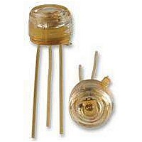
OPF520 Optek, OPF520 Datasheet - Page 2

OPF520
Manufacturer Part Number
OPF520
Description
Fiber Optic Transmitters, Receivers, Transceivers Fiber Optic Receiver 5Mb
Manufacturer
Optek
Datasheet
1.OPF520.pdf
(8 pages)
Specifications of OPF520
For Use With Fiber Type
Singlemode
Function
High performance receiver for data communication
Product
Receiver
Maximum Rise Time
30 ns
Maximum Fall Time
30 ns
Pulse Width Distortion
30 %
Maximum Output Current
25 mA
Operating Supply Voltage
- 0.5 V to + 7 V
Maximum Operating Temperature
+ 85 C
Minimum Operating Temperature
- 40 C
For Use With
Singlemode Fiber
Lead Free Status / RoHS Status
Lead free / RoHS Compliant
Absolute Maximum Ratings
Fiber Optic Receiver
OPF520
Output Current
Output Voltage
Electrical/Optical Characteristics
4.75 ≤ V
Notes:
1.
2.
3.
Operating Temperature
Lead Soldering Temperature (for 10 seconds)
Storage Temperature
Open Collector Power Distribution
Fan Out (TTL)
Issue B
Page 2 of 8
Supply Voltage
SYMBOL
RoHS
P
P
PWD
t
t
I
V
I
t
PDHL
PDLH
I
OC(H)
CCH
OC(L)
8mA load (5 x 1.6 mA), R
Use recommended test circuit below, but connect V
to an independent voltage source with R
Use recommended test circuit below.
CCL
r
OH
, t
OL
f
CC
12/2010
≤ 5.25, Fiber Sizes ≤ 200µm, NA ≤ 0.35, T
High Level Output Current
Low Level Output Voltage
Supply Current, Output High
Supply Current, Output Low
Peak Input Power Level, Output High
(Guaranteed Output High)
Peak Input Power Level, Output Low
(Guaranteed Output Low)
Rise, Fall Time
Propagation Delay, Output High to Low
Propagation Delay, Output Low to High
Pulse Width Distortion
OPTEK reserves the right to make changes at any time in order to improve design and to supply the best product possible.
PARAMETER
L
= 560 Ω
L
= 0.
A
= 25°C unless otherwise specified
O
-25.4
MIN
2.9
-24
4.0
Phone: (800) 341-4747 FAX: (972) 323– 2396 sensors@optekinc.com www.optekinc.com
TYP
100
±30
0.2
3.5
6.9
30
65
5
MAX
250
-9.2
120
100
-40
-10
0.5
6.3
0.1
10
Recommended Test Circuit
OPTEK Technology Inc.— 1645 Wallace Drive, Carrollton, Texas 75006
UNITS
dBm
dBm
dBm
mA
mA
µW
µW
µW
µA
ns
ns
ns
%
V
V
I
V
V
λp = 850 nm
λp = 850 nm, I
λp = 850 nm, I
-40ºC ≤ T
P
O
O
CC
CC
OC
= 8 mA, P
= 18V, P
= 5.25 V, P
= 5.25 V, P
= 20 dBm (peak), ƒ = 2.5 MHz, See Note 3
A
≤ +85ºC
OC
OC
O
O
< -40 dBm, See Note 2
> +24 dBm, See Note2
OC
OC
CONDITIONS
= 8 mA
= 8 mA
< -40 dBm, See Note 2
< -24 dBm, See Note 2
-55° C to +115° C
-0.5 V to +18.0 V
-40° C to +85° C
-0.5 V to +7.0 V
260° C
25 mA
40mW
5
(1)


