BPW96B Vishay, BPW96B Datasheet - Page 2
BPW96B
Manufacturer Part Number
BPW96B
Description
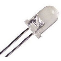
Photodetector Transistors NPN Phototransistor 70V 150mW 850nm
Manufacturer
Vishay
Type
Chipr
Datasheet
1.BPW96B.pdf
(5 pages)
Specifications of BPW96B
Maximum Power Dissipation
150 mW
Maximum Dark Current
200 nA
Collector- Emitter Voltage Vceo Max
70 V
Maximum Operating Temperature
+ 100 C
Minimum Operating Temperature
- 40 C
Package / Case
T-1 3/4
Transistor Polarity
NPN
Wavelength Typ
850nm
Power Consumption
150mW
Viewing Angle
20°
No. Of Pins
2
Light Current
4.5mA
Dark Current
200nA
C-e Breakdown Voltage
70V
Current Rating
50mA
Phototransistor Type
Phototransistor
Polarity
NPN
Number Of Elements
1
Lens Type
Clear
Emitter-collector Voltage (max)
5V
Collector-emitter Voltage
70V
Collector Current (dc) (max)
50mA
Collector-emitter Sat Volt (max)
0.3V
Dark Current (max)
200nA
Power Dissipation
150mW
Peak Wavelength
850nm
Half-intensity Angle
40deg
Operating Temp Range
-40C to 100C
Operating Temperature Classification
Industrial
Mounting
Through Hole
Pin Count
2
Package Type
T-1 3/4
Lead Free Status / RoHS Status
Lead free / RoHS Compliant
Lead Free Status / RoHS Status
Lead free / RoHS Compliant, Lead free / RoHS Compliant


BPW96B, BPW96C
Vishay Semiconductors
Note
T
www.vishay.com
420
amb
BASIC CHARACTERISTICS
PARAMETER
Collector emitter breakdown voltage
Collector emitter dark current
Collector emitter capacitance
Angle of half sensitivity
Wavelength of peak sensitivity
Range of spectral bandwidth
Collector emitter saturation voltage
Turn-on time
Turn-off time
Cut-off frequency
TYPE DEDICATED CHARACTERISTICS
PARAMETER
Collector light current
Fig. 1 - Power Dissipation Limit vs. Ambient Temperature
= 25 °C, unless otherwise specified
94 8300
200
160
120
80
40
0
0
T
amb
20
- Ambient Temperature (°C)
40
For technical questions, contact: detectortechsupport@vishay.com
E
60
V
V
V
e
S
S
S
E
V
= 1 mW/cm
Silicon NPN Phototransistor, RoHS Compliant
e
= 5 V, I
= 5 V, I
= 5 V, I
CE
TEST CONDITION
= 1 mW/cm
TEST CONDITION
R
= 5 V, f = 1 MHz, E = 0
V
80
thJA
CE
V
I
CE
C
C
C
C
I
= 20 V, E = 0
C
= 5 mA, R
= 5 mA, R
= 5 mA, R
= 0.1 mA
= 5 V
= 1 mA
2
, λ = 950 nm,
100
2
, λ = 950 nm,
L
L
L
= 100 Ω
= 100 Ω
= 100 Ω
BPW96C
BPW96B
PART
SYMBOL
V
V
(BR)CEO
C
I
λ
CEO
CEsat
t
t
CEO
λ
ϕ
f
0.1
on
off
c
p
SYMBOL
I
I
ca
ca
MIN.
70
MIN.
2.5
4.5
450 to 1080
TYP.
± 20
850
180
2.0
2.3
1
3
TYP.
4.5
8
Document Number: 81532
MAX.
200
0.3
MAX.
Rev. 1.7, 05-Sep-08
7.5
15
UNIT
kHz
UNIT
deg
nm
nm
nA
pF
µs
µs
mA
mA
V
V
Related parts for BPW96B
Image
Part Number
Description
Manufacturer
Datasheet
Request
R

Part Number:
Description:
Photodetector Transistors NPN Phototransistor 70V 150mW 850nm
Manufacturer:
Vishay
Datasheet:

Part Number:
Description:
Photodetector Transistors PHOTODIODE
Manufacturer:
OSRAM Opto Semiconductors Inc
Part Number:
Description:
Photodetector Transistors PHOTODIODE
Manufacturer:
OSRAM Opto Semiconductors Inc
Part Number:
Description:
357-036-542-201 CARDEDGE 36POS DL .156 BLK LOPRO
Manufacturer:
Vishay
Datasheet:
Part Number:
Description:
357-036-542-201 CARDEDGE 36POS DL .156 BLK LOPRO
Manufacturer:
Vishay
Datasheet:
Part Number:
Description:
357-036-542-201 CARDEDGE 36POS DL .156 BLK LOPRO
Manufacturer:
Vishay
Datasheet:
Part Number:
Description:
357-036-542-201 CARDEDGE 36POS DL .156 BLK LOPRO
Manufacturer:
Vishay
Datasheet:
Part Number:
Description:
357-036-542-201 CARDEDGE 36POS DL .156 BLK LOPRO
Manufacturer:
Vishay
Datasheet:
Part Number:
Description:
357-036-542-201 CARDEDGE 36POS DL .156 BLK LOPRO
Manufacturer:
Vishay
Datasheet:
Part Number:
Description:
357-036-542-201 CARDEDGE 36POS DL .156 BLK LOPRO
Manufacturer:
Vishay
Datasheet:
Part Number:
Description:
357-036-542-201 CARDEDGE 36POS DL .156 BLK LOPRO
Manufacturer:
Vishay
Datasheet:
Part Number:
Description:
357-036-542-201 CARDEDGE 36POS DL .156 BLK LOPRO
Manufacturer:
Vishay
Datasheet:
Part Number:
Description:
357-036-542-201 CARDEDGE 36POS DL .156 BLK LOPRO
Manufacturer:
Vishay
Datasheet:
Part Number:
Description:
357-036-542-201 CARDEDGE 36POS DL .156 BLK LOPRO
Manufacturer:
Vishay
Datasheet:
Part Number:
Description:
357-036-542-201 CARDEDGE 36POS DL .156 BLK LOPRO
Manufacturer:
Vishay
Datasheet: