216843-1 TE Connectivity, 216843-1 Datasheet - Page 25
216843-1
Manufacturer Part Number
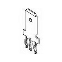
216843-1
Description
.250 POS LOCK TAB
Manufacturer
TE Connectivity
Type
Power Tapr
Datasheet
1.216843-1.pdf
(111 pages)
Specifications of 216843-1
Gender
RCP
Body Orientation
Straight
Number Of Contacts
1POS
Number Of Ports
1Port
Number Of Terminals
3
Current Rating (max)
15/ContactA
Pitch (mm)
Not Requiredmm
Contact Material
Phosphor Bronze
Mounting Style
Through Hole
Termination Method
Solder
Contact Plating
Tin Over Nickel
Profile
Standard
Insulation
No
Pcb Mounting Orientation
Vertical
Mating Area Interface Dimensions (mm [in])
6.35 x 0.81 [.250 x .032]
Current Rating (a)
15
Faston Tab
Without
Screw
Without
Louvertac Band
Without
Number Of Positions
3
Washer
Without
Holes
With
Contact Configuration
ACTION PIN Post, High Current
Action Pin Material
Phosphor Bronze
Action Pin Plating
Tin over Nickel
Rohs/elv Compliance
RoHS compliant, ELV compliant
Lead Free Solder Processes
Not relevant for lead free process
Rohs/elv Compliance History
Always was RoHS compliant
Pcb Thickness, Recommended (mm [in])
1.57 – 3.18 [0.062 – 0.1251]
Packaging Method
Loose Piece
Lead Free Status / RoHS Status
Compliant


86
Housings
(Hermaphroditic),
24 Positions
Material
Housing — Glass-filled polybutylene
terephthalate (PBT), blue
Bushing — Brass, zinc-plated
Related Product Data
Performance Specifications —
page 85
MIC Contacts — page 87
Crimp Snap-In Contacts — page 87
Technical Documents
Product Specification
108-5371
Catalog 1773096
Revised 2-10
www.tycoelectronics.com
Recommended Panel Cutout
Dimensions are in inches and
millimeters unless otherwise
specified. Values in brackets
are metric equivalents.
Power Connectors & Interconnection Systems
Hybrid Blind-Mate Drawer Connectors
Note: All part numbers are RoHS compliant.
[11.22]
[11.80]
.441
.440
[5.00]
.197
[70.00]
2.756
[45.00]
[60.80]
1.771
2.394
Pitch
Dimensions are shown for
reference purposes only.
Specifications subject
to change.
Signal Circuits
Upward and downward = Axial clearance
Circumferential = Floating
Up- and downward = 0.05 [.002]
Up- and downward = 0.30 [.012]
*Dimensions applicable for rear mounting.
[12.22]
[12.18]
Circumferential = 0.14 [.006]
Circumferential = 0.80 [.031]
.481
.480
Floating of Bushing
[5.00]
.197*
[6.10]
0.24
[30.00]
Power Circuits
1.181
[17.9]
0.70
(4 corners)
.197*
[5.00]
[29.1]
1.15
[72.00]
[60.80]
[54.80]
[49.60]
2.835
2.394
USA: 1-800-522-6752
Canada: 1-905-470-4425
Mexico: 01-800-733-8926
C. America: 52-55-1106-0803
2.157
1.953
[2.50]
.098
(Continued)
R*
Note: Reverse figures show circuit numbers.
(Example =
B13
A1
A13
B1
Panel Mounting Position
All Corners
Part Numbers
[3.300]
.130
5176916-1
5176916-2
(Front Mounting)
Housing
R1
Dia.
[32.00]
1.260
B14
A2
used for No. 13 on the reverse side.)
[9.60]
B13
A14
A1
.378
B2
South America: 55-11-2103-6000
Hong Kong: 852-2735-1628
Japan: 81-44-844-8013
UK: 44-(0)8002-67666
The hole used for No. 1 circuit is
A23
B11
A11
B23
Related parts for 216843-1
Image
Part Number
Description
Manufacturer
Datasheet
Request
R

Part Number:
Description:
Printers THERMAL PRINTER HS-SLEEVE MARKER
Manufacturer:
TE Connectivity


Part Number:
Description:
High Speed / Modular Connectors 30P HEADER ASSY
Manufacturer:
TE Connectivity
Datasheet:

Part Number:
Description:
High Speed / Modular Connectors REC 6X005P R/A LT B-PLANE HS3
Manufacturer:
TE Connectivity
Datasheet:

Part Number:
Description:
High Speed / Modular Connectors 2MM HM RCPT 50P R/A AU
Manufacturer:
TE Connectivity
Datasheet:

Part Number:
Description:
High Speed / Modular Connectors 2MM HM RCPT 50P R/A AU
Manufacturer:
TE Connectivity
Datasheet:


Part Number:
Description:
Manufacturer:
TE Connectivity
Datasheet:


Part Number:
Description:
Manufacturer:
TE Connectivity
Datasheet:

Part Number:
Description:
Manufacturer:
TE Connectivity
Datasheet:

Part Number:
Description:
Manufacturer:
TE Connectivity
Datasheet: