216843-1 TE Connectivity, 216843-1 Datasheet - Page 56
216843-1
Manufacturer Part Number
216843-1
Description
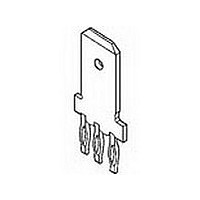
.250 POS LOCK TAB
Manufacturer
TE Connectivity
Type
Power Tapr
Datasheet
1.216843-1.pdf
(111 pages)
Specifications of 216843-1
Gender
RCP
Body Orientation
Straight
Number Of Contacts
1POS
Number Of Ports
1Port
Number Of Terminals
3
Current Rating (max)
15/ContactA
Pitch (mm)
Not Requiredmm
Contact Material
Phosphor Bronze
Mounting Style
Through Hole
Termination Method
Solder
Contact Plating
Tin Over Nickel
Profile
Standard
Insulation
No
Pcb Mounting Orientation
Vertical
Mating Area Interface Dimensions (mm [in])
6.35 x 0.81 [.250 x .032]
Current Rating (a)
15
Faston Tab
Without
Screw
Without
Louvertac Band
Without
Number Of Positions
3
Washer
Without
Holes
With
Contact Configuration
ACTION PIN Post, High Current
Action Pin Material
Phosphor Bronze
Action Pin Plating
Tin over Nickel
Rohs/elv Compliance
RoHS compliant, ELV compliant
Lead Free Solder Processes
Not relevant for lead free process
Rohs/elv Compliance History
Always was RoHS compliant
Pcb Thickness, Recommended (mm [in])
1.57 – 3.18 [0.062 – 0.1251]
Packaging Method
Loose Piece
Lead Free Status / RoHS Status
Compliant


Product Facts
I
I
I
I
I
I
I
I
I
■
I
For more information,
request Catalog 1308885.
Catalog 1773096
Revised 2-10
www.tycoelectronics.com
Certified by Canadian
Standards Association,
File No. LR7189
Rated to 600 VAC (RMS)
Flame retardant housings
94V-0
Housings, adapters, and
power terminals keyed for
proper assembly
Stackable housings provide
easy wire routing and neat
wire dressing
Built-in interlocking
features better resist shock
and vibration
Usable as in-line connector,
or as panel and surface-
mount connector
Available in six different
colors for circuit coding
and identification
Choice of two power
terminals accommodates
10-12 AWG and 14-16-18
AWG conductors
Recognized under the
Component Program of
Underwriters
Laboratories Inc.,
File No. E28476
VDE Registered #5133
Dimensions are in inches and
millimeters unless otherwise
specified. Values in brackets
are metric equivalents.
R
R
Power Connectors & Interconnection Systems
AMPINNERGY Wire-To-Wire Connectors
AMPINNERGY wire-to-wire
(WTW) Connectors provide
a reliable and efficient
means of interconnecting
conductors employed to
carry up to 600 VAC in
power circuits or networks.
The WTW connectors con-
sist of mating hermaphro-
ditic, flame retardant
polycarbonate housings
into which customer termi-
nated power contacts are
inserted. Stackable in four
directions through the use
of molded interlocking key-
ways, the connectors make
wire routing and dressing
orderly and easy to accom-
plish. More importantly, the
built-in interlocking features
on the connectors and the
accessory mounting
adapters provide better
resistance to the effects of
shock and vibration, keep-
ing the interconnect more
stable and secure.
The design features of the
WTW connector make it
easily applicable to free-
hanging, surface mounted
or panel mounted applica-
tions. By simply sliding the
accessory mounting
adapters into the molded
keyways of the connector
housing, a free-hanging
connector can be trans-
Dimensions are shown for
reference purposes only.
Specifications subject
to change.
formed into a surface-
mount connector or a
panel-mount connector.
Customer supplied 8-32
screws and nuts may be
used to secure the connec-
tors configured with the
mounting adapters to
printed circuit boards or
distribution panels. The
same hardware may be
used to secure the connec-
tors to pre-cut openings in
the panels.
Furthermore, WTW connec-
tor housings, mounting
adapters and power termi-
nals are all provided with
alignment or keying fea-
tures that make it difficult to
improperly assemble and
apply the connector.
Alignment slots and tabs
on the plastic connector
housings provide for easy
mating of the housings,
even in the dark! Mounting
adapters have a keyway on
one side and a key on the
other side providing for
easy assembly to the con-
nector by touch alone if
necessary. And the power
terminals have a side tab
that helps prevent the
incorrect insertion of the
terminated conductor into
the housing. Once
inserted, the contacts
USA: 1-800-522-6752
Canada: 1-905-470-4425
Mexico: 01-800-733-8926
C. America: 52-55-1106-0803
firmly latch within the con-
nector housing.
The WTW connector sys-
tem is available in six dif-
ferent and distinctive colors
which makes circuit differ-
entiation and identification
possible. The crimped
power terminals will
accommodate either
10-12 AWG or 14-16-18 AWG
stranded conductors.
Depending upon the con-
ductor size and the num-
ber of conductors in the
connector configuration,
the current rating ranges
from 10 Amps to 55 Amps.
Technical Documents
Product Specification
108-1373 AMPINNERGY WTW
Connectors
Application Specification
114-6051
Instruction Sheets
408-3277 AMPINNERGY Wire-To-Wire
Stackable Connectors
408-3198 Inspection of AMPINNERGY
System Power Contacts
South America: 55-11-2103-6000
Hong Kong: 852-2735-1628
Japan: 81-44-844-8013
UK: 44-(0)8002-67666
117
Related parts for 216843-1
Image
Part Number
Description
Manufacturer
Datasheet
Request
R

Part Number:
Description:
Printers THERMAL PRINTER HS-SLEEVE MARKER
Manufacturer:
TE Connectivity


Part Number:
Description:
High Speed / Modular Connectors 30P HEADER ASSY
Manufacturer:
TE Connectivity
Datasheet:

Part Number:
Description:
High Speed / Modular Connectors REC 6X005P R/A LT B-PLANE HS3
Manufacturer:
TE Connectivity
Datasheet:

Part Number:
Description:
High Speed / Modular Connectors 2MM HM RCPT 50P R/A AU
Manufacturer:
TE Connectivity
Datasheet:

Part Number:
Description:
High Speed / Modular Connectors 2MM HM RCPT 50P R/A AU
Manufacturer:
TE Connectivity
Datasheet:


Part Number:
Description:
Manufacturer:
TE Connectivity
Datasheet:


Part Number:
Description:
Manufacturer:
TE Connectivity
Datasheet:

Part Number:
Description:
Manufacturer:
TE Connectivity
Datasheet:

Part Number:
Description:
Manufacturer:
TE Connectivity
Datasheet: