216843-1 TE Connectivity, 216843-1 Datasheet - Page 3
216843-1
Manufacturer Part Number
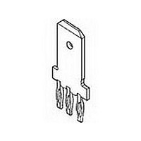
216843-1
Description
.250 POS LOCK TAB
Manufacturer
TE Connectivity
Type
Power Tapr
Datasheet
1.216843-1.pdf
(111 pages)
Specifications of 216843-1
Gender
RCP
Body Orientation
Straight
Number Of Contacts
1POS
Number Of Ports
1Port
Number Of Terminals
3
Current Rating (max)
15/ContactA
Pitch (mm)
Not Requiredmm
Contact Material
Phosphor Bronze
Mounting Style
Through Hole
Termination Method
Solder
Contact Plating
Tin Over Nickel
Profile
Standard
Insulation
No
Pcb Mounting Orientation
Vertical
Mating Area Interface Dimensions (mm [in])
6.35 x 0.81 [.250 x .032]
Current Rating (a)
15
Faston Tab
Without
Screw
Without
Louvertac Band
Without
Number Of Positions
3
Washer
Without
Holes
With
Contact Configuration
ACTION PIN Post, High Current
Action Pin Material
Phosphor Bronze
Action Pin Plating
Tin over Nickel
Rohs/elv Compliance
RoHS compliant, ELV compliant
Lead Free Solder Processes
Not relevant for lead free process
Rohs/elv Compliance History
Always was RoHS compliant
Pcb Thickness, Recommended (mm [in])
1.57 – 3.18 [0.062 – 0.1251]
Packaging Method
Loose Piece
Lead Free Status / RoHS Status
Compliant


64
Catalog 1773096
Revised 2-10
www.tycoelectronics.com
If you selected a standard drawer connector for your appli-
cation, before placing an order you need to specify your
application-specific requirements, such as housing type,
contact loading, and termination style. Layout forms for all
standard drawer connectors, such as the one shown below,
are available online at http://www.tycoelectronics.com or
can be obtained from Tyco Electronics customer service for
Pin Assembly
1. Choose one housing from the Pin Housing Selection Menu table. Place
2. Write the total quantity of each pin contact you require for each pin
3. Crimp contacts are shipped uninstalled. Threaded and PCB tail
4. Sign, date and send the completed form to your local Tyco Electronics
an X in the appropriate guide pin circles, if guide pins are required.
assembly in the Qty column of the Pin Contact Selection Menu table.
contacts are installed by Tyco Electronics; enter the letter reference
of the desired contact in the appropriate contact positions on the
drawing: e.g., if you need a size #20 premate PCB tail standard con-
tact to be installed in contact position #10, write “Q” in circle #10.
Sales Engineer.
11
19
27
3
35
41
47
50
G3
G1
Pin Connector Rear Face Cavity Identification
12
20
28
4
1
42
36
Assigned by Tyco Electronics
13
21
29
Top Assembly Part Number
5
Pin Connector (Rear Face)
Pin Contact Insertion Side
Dimensions are in inches and
millimeters unless otherwise
specified. Values in brackets
are metric equivalents.
37
43
14
30
22
6
48
51
15
23
31
7
38
44
Power Connectors & Interconnection Systems
How to Tailor Your ELCON Drawer Connector
16
24
32
8
45
39
17
25
33
9
2
G2
G4
49
52
40
46
10
18
34
26
Dimensions are shown for
reference purposes only.
Specifications subject
to change.
Size #0
Size #20
Size #16
Size #12 or
#12HP
Crimp and Threaded contacts are removable. PCB tail contacts are non-removable.
#12 Hot-
Pin Housing Selection Menu
Part Number
1648183-1
Pin Contact Selection Menu
Float-Mount Shoulder Screw
Plug
Size
Part Number
#20
#16
#12
#0
1650399-1
1650401-1
Submit to your local Tyco Electronics Sales Engineer.
this purpose. Complete a form for the pin and socket side
of your connector as indicated in the instructions and fax it
to your Tyco Electronics sales engineer. We will issue a
unique part number specific to your configuration, which
you can then use to place orders. Samples and customer
drawings are also available upon request.
Company
Contact Name
Telephone
Email Address
I am: ❏ End user
Signature
Ref. Part Number
A
B
C
D = 1766274-1
E
F
G = 1766268-1
H = 1766231-1
J
K
L
M = 1650161-1
N = 1650162-2
P
Q = 1650065-1
R = 1650226-1
S
T
U = 1766199-2
V
W = 1766223-1
X
Y
Z
AA = 1766196-1
AB = 1766245-1
AC = 1766250-1
AD = 1766249-1
AE = 1650153-2
AF = 1650156-2
AG = 1650060-2
AH = 1650074-3
❏ Contract manufacturer (end user:
= 1766811-1
= 1766819-1
= 1766230-1
= 1766269-1
= 1766275-1
= 1766270-1
= 1766276-1
= 1650155-1
= 1650283-1
= 1766196-1
= 1766198-1
= 1766222-1
= 1766818-1
= 1766193-1
= 1766195-1
USA: 1-800-522-6752
Canada: 1-905-470-4425
Mexico: 01-800-733-8926
C. America: 52-55-1106-0803
Description
Housing without guides
Housing with guides (#6-32 thread)
Housing with guides (M3 x 0.5 thread)
Description
Screw, No 10-32 UNC 2A
Screw, M5 x 0.8
ENTER CUSTOMER INFORMATION
Termination Style & Pin Length
Crimp
Probe Proof, crimp
1/4-20 Internal Thread
M6 x 1 Internal Thread
Probe Proof, 1/4-20 Internal Thread
Probe Proof, M6 x 1 Internal Thread
1/4-20 External Thread
M6 x 1 External Thread
Probe Proof, 1/4-20 External Thread
Probe Proof, M6 x 1 External Thread
Crimp, standard
Crimp, premate
Crimp, postmate
PCB tail, standard
PCB tail, premate
PCB tail, postmate
Crimp, standard
Crimp, premate
Crimp, postmate
PCB tail, standard
PCB tail, premate
PCB tail, postmate
Crimp, standard
Crimp, premate
Crimp, postmate
PCB tail, standard
PCB tail, premate
PCB tail, postmate
Crimp, standard, Hot-Plug
Crimp, premate, Hot-Plug
PCB tail, standard, Hot-Plug
PCB tail, premate, Hot-Plug
Location
Title
Fax
Today’s Date
Annual Quantity Required
South America: 55-11-2103-6000
Hong Kong: 852-2735-1628
Japan: 81-44-844-8013
UK: 44-(0)8002-67666
Check
Qty.
One
Qty.
)
Related parts for 216843-1
Image
Part Number
Description
Manufacturer
Datasheet
Request
R

Part Number:
Description:
Printers THERMAL PRINTER HS-SLEEVE MARKER
Manufacturer:
TE Connectivity


Part Number:
Description:
High Speed / Modular Connectors 30P HEADER ASSY
Manufacturer:
TE Connectivity
Datasheet:

Part Number:
Description:
High Speed / Modular Connectors REC 6X005P R/A LT B-PLANE HS3
Manufacturer:
TE Connectivity
Datasheet:

Part Number:
Description:
High Speed / Modular Connectors 2MM HM RCPT 50P R/A AU
Manufacturer:
TE Connectivity
Datasheet:

Part Number:
Description:
High Speed / Modular Connectors 2MM HM RCPT 50P R/A AU
Manufacturer:
TE Connectivity
Datasheet:


Part Number:
Description:
Manufacturer:
TE Connectivity
Datasheet:


Part Number:
Description:
Manufacturer:
TE Connectivity
Datasheet:

Part Number:
Description:
Manufacturer:
TE Connectivity
Datasheet:

Part Number:
Description:
Manufacturer:
TE Connectivity
Datasheet: