TCET1106G Vishay, TCET1106G Datasheet - Page 5
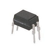
TCET1106G
Manufacturer Part Number
TCET1106G
Description
Transistor Output Optocouplers Phototransistor Out Single CTR 100-300%
Manufacturer
Vishay
Datasheet
1.TCET1103.pdf
(9 pages)
Specifications of TCET1106G
Isolation Voltage
5000 Vrms
Maximum Input Diode Current
60 mA
Maximum Reverse Diode Voltage
6 V
Output Device
Phototransistor
Output Type
DC
Configuration
1 Channel
Input Type
DC
Maximum Collector Emitter Voltage
70 V
Maximum Collector Emitter Saturation Voltage
0.3 V
Current Transfer Ratio
300 %
Maximum Forward Diode Voltage
1.6 V
Maximum Collector Current
50 mA
Maximum Power Dissipation
265 mW
Maximum Operating Temperature
+ 100 C
Minimum Operating Temperature
- 40 C
Package / Case
PDIP-4
No. Of Channels
1
Optocoupler Output Type
Phototransistor
Input Current
50mA
Output Voltage
70V
Opto Case Style
DIP
No. Of Pins
4
Mounting Type
Through Hole
Lead Free Status / RoHS Status
Lead free / RoHS Compliant
Available stocks
Company
Part Number
Manufacturer
Quantity
Price

Part Number:
TCET1106G
Manufacturer:
VISHAY/威世
Quantity:
20 000


TCET1100, TCET1100G
Vishay Semiconductors
www.vishay.com
814
SWITCHING CHARACTERISTICS
PARAMETER
Delay time
Rise time
Turn-on time
Storage time
Fall time
Turn-off time
Turn-on time
Turn-off time
95 10804
94 9182
0
R
t
T
p
t
Fig. 3 - Test Circuit, Non-Saturated Operation
G
p
= 50 µs
= 0.01
= 50 Ω
300
250
200
150
100
50
0
I
F
0
Fig. 1 - Derating Diagram
50 Ω
I
T
F
25
si
- Safety Temperature (°C)
IR-diode
I
si
50
100 Ω
(mA)
P
Phototransistor
si
75
V
V
V
V
V
V
V
V
S
S
S
S
S
S
S
S
(mW)
For technical questions, contact:
+ 5 V
= 5 V, I
= 5 V, I
= 5 V, I
= 5 V, I
= 5 V, I
= 5 V, I
= 5 V, I
= 5 V, I
I
Channel II
C
Channel I
100
= 2 mA; adjusted through
TEST CONDITION
Optocoupler, Phototransistor Output,
(see figure 3)
(see figure 3)
(see figure 3)
(see figure 3)
(see figure 3)
(see figure 3)
(see figure 4)
(see figure 4)
C
C
C
C
C
C
F
F
125
= 2 mA, R
= 2 mA, R
= 2 mA, R
= 2 mA, R
= 2 mA, R
= 2 mA, R
= 10 mA, R
= 10 mA, R
input amplitude
Oscilloscope
R
C
150
L
L
= 1 MΩ
= 20 pF
High Temperature
L
L
L
L
L
L
L
L
= 100 Ω,
= 100 Ω,
= 100 Ω,
= 100 Ω,
= 100 Ω,
= 100 Ω,
= 1 kΩ,
= 1 kΩ,
optocoupleranswers@vishay.com
SYMBOL
t
t
t
t
t
t
t
on
t
off
on
off
d
s
Fig. 2 - Test Pulse Diagram for Sample Test According to
r
f
95 10843
0
R
t
T
p
13930
t
V
G
p
V
V
IOWM
= 0.01
= 50 µs
IOTM
IORM
= 50 Ω
V
DIN EN 60747-5-5/DIN EN 60747-; IEC 60747
Pd
0
Fig. 4 - Test Circuit, Saturated Operation
I
F
t
1
50 Ω
I
MIN.
F
= 10 mA
t
t
t
1
3
stres
t
, t
, t
test
1 kΩ
2
4
t
Tr
= 1 to 10 s
= 1 s
= 10 s
= 12 s
= 60 s
TYP.
0.3
4.7
10
3
3
6
5
9
+ 5 V
I
Channel II
C
Channel I
Document Number: 83503
MAX.
Rev. 2.3, 14-Oct-09
t
2
t
3
R
C
t
Oscilloscope
t
test
stres
L
L
≥
≤
t
t
4
1 MΩ
20 pF
UNIT
µs
µs
µs
µs
µs
µs
µs
µs
Related parts for TCET1106G
Image
Part Number
Description
Manufacturer
Datasheet
Request
R

Part Number:
Description:
357-036-542-201 CARDEDGE 36POS DL .156 BLK LOPRO
Manufacturer:
Vishay
Datasheet:
Part Number:
Description:
357-036-542-201 CARDEDGE 36POS DL .156 BLK LOPRO
Manufacturer:
Vishay
Datasheet:
Part Number:
Description:
357-036-542-201 CARDEDGE 36POS DL .156 BLK LOPRO
Manufacturer:
Vishay
Datasheet:
Part Number:
Description:
357-036-542-201 CARDEDGE 36POS DL .156 BLK LOPRO
Manufacturer:
Vishay
Datasheet:
Part Number:
Description:
357-036-542-201 CARDEDGE 36POS DL .156 BLK LOPRO
Manufacturer:
Vishay
Datasheet:
Part Number:
Description:
357-036-542-201 CARDEDGE 36POS DL .156 BLK LOPRO
Manufacturer:
Vishay
Datasheet:
Part Number:
Description:
357-036-542-201 CARDEDGE 36POS DL .156 BLK LOPRO
Manufacturer:
Vishay
Datasheet:
Part Number:
Description:
357-036-542-201 CARDEDGE 36POS DL .156 BLK LOPRO
Manufacturer:
Vishay
Datasheet:
Part Number:
Description:
357-036-542-201 CARDEDGE 36POS DL .156 BLK LOPRO
Manufacturer:
Vishay
Datasheet:
Part Number:
Description:
357-036-542-201 CARDEDGE 36POS DL .156 BLK LOPRO
Manufacturer:
Vishay
Datasheet:
Part Number:
Description:
357-036-542-201 CARDEDGE 36POS DL .156 BLK LOPRO
Manufacturer:
Vishay
Datasheet:
Part Number:
Description:
357-036-542-201 CARDEDGE 36POS DL .156 BLK LOPRO
Manufacturer:
Vishay
Datasheet:
Part Number:
Description:
357-036-542-201 CARDEDGE 36POS DL .156 BLK LOPRO
Manufacturer:
Vishay
Datasheet:
Part Number:
Description:
357-036-542-201 CARDEDGE 36POS DL .156 BLK LOPRO
Manufacturer:
Vishay
Datasheet:
Part Number:
Description:
357-036-542-201 CARDEDGE 36POS DL .156 BLK LOPRO
Manufacturer:
Vishay
Datasheet: