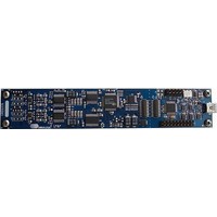
CRD-5376 Cirrus Logic Inc, CRD-5376 Datasheet - Page 25

CRD-5376
Manufacturer Part Number
CRD-5376
Description
Audio Modules & Development Tools Ref Bd LP Mlt-Ch Decimation Filter
Manufacturer
Cirrus Logic Inc
Datasheet
1.CRD-5376.pdf
(68 pages)
Specifications of CRD-5376
Description/function
Audio D/A
Operating Supply Voltage
3.3 V
Product
Audio Modules
Supply Current
300 mA
For Use With/related Products
CS3301A, CS3302A, CS4373A, CS5371A, CS5372A, CS5376A
Lead Free Status / RoHS Status
Lead free / RoHS Compliant
2.3.2.5
By default, the C8051F320 microcontroller sends the TIMEB signal to the digital filter for the first collected
sample of a data record. By default, 100 initial samples are skipped during data collection to ensure the
CS5376A digital filters are fully settled, and the timebreak signal is automatically set for the first ‘real’ col-
lected sample.
2.3.2.6
Through the PC evaluation software, the microcontroller default firmware can be automatically flashed to
the latest version without connecting an external programmer. To flash custom firmware, software tools
and an inexpensive hardware programmer that connects to the C2 Debug Interface on CRD5376 is avail-
able for purchase from Silicon Laboratories (DEBUGADPTR1-USB).
2.3.3
To make synchronous analog measurements throughout a distributed system, a synchronous system
clock is required to be provided to each measurement node. CRD5376 can receive a lower frequency sys-
tem clock through the external connector and create a synchronous higher frequency clock using an on-
board PLL.
The expected input clock frequency to the external connector is set by jumper options. If no external clock
is supplied to CRD5376, the PLL will free-run at the nominal output frequency. A jumper option is available
to output the clock to the external connector, making it the system clock source.
DS612RD2
Specification
Input Clock Frequency
Distributed Clock Synchronization
Maximum Input Clock Jitter, RMS
Specification
PLL Output Clock Frequency
Maximum Output Jitter, RMS
Oscillator Type
Detector Architecture
Phase Locked Loop
Timebreak Signal
C2 Debug Interface
Input Clock
1.024 MHz
2.048 MHz
4.096 MHz
Table 8. Clock Input / Output Jumper Settings
Jumper
R16
R18
R82
Output Clock
1.024 MHz
2.048 MHz
4.096 MHz
Value
1.024, 2.048, 4.096 MHz
± 240 ns
1 ns
Value
32.768 MHz
300 ps
VCXO
Phase / Frequency
R68 + R16
R68 + R18
R68 + R82
Jumpers
CRD5376
25


