XR21V1410IL-0C-EB Exar Corporation, XR21V1410IL-0C-EB Datasheet - Page 21
XR21V1410IL-0C-EB
Manufacturer Part Number
XR21V1410IL-0C-EB
Description
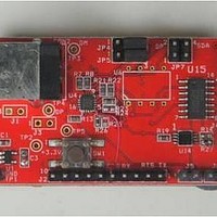
Interface Modules & Development Tools For XR21V1410 QFN16 USB, RS485;No Cables
Manufacturer
Exar Corporation
Series
-r
Specifications of XR21V1410IL-0C-EB
Interface Type
RS-232, USB
Operating Supply Voltage
3.3 V
Product
Interface Modules
Silicon Core Number
XR21V1410
Application Sub Type
UART
Kit Contents
Board
Main Purpose
Interface, USB 2.0 to UART
Embedded
No
Utilized Ic / Part
XR21V1410IL
Primary Attributes
-
Secondary Attributes
-
Silicon Manufacturer
Exar
Kit Application Type
Communication & Networking
For Use With/related Products
XR21V1410
Lead Free Status / RoHS Status
Lead free / RoHS Compliant


REV. 1.2.0
ERROR_STATUS[4]: Framing Error
ERROR_STATUS[5]: Parity Error
ERROR_STATUS[6]: Overrun Error
ERROR_STATUS[7]: Break Status
Writing a non-zero value to this register causes a break condition to be generated continuously until the
register is cleared. If data is being shifted out of the TX pin, the data will be completely shifted out before the
break condition is generated.
XCVR_EN_DELAY[3:0]: Turn-around delay
This is the number of bit times to wait before changing the direction of the transceiver from transmit to receive
when half-duplex mode is enabled.
XCVR_EN_DELAY[3:0]: Reserved
These bits are reserved and should be ’0’.
GPIO_MODE[2:0]: GPIO Mode Select
There are 4 modes of operation for the GPIOs. The descriptions can be found in
page
3.3.10
3.3.11
3.3.12
BITS
[2:0]
Logic 0 = No framing error
Logic 1 = A framing error has been detected (clears after read). A framing error occurs when a stop bit is not
present when it is expected.
Logic 0 = No parity error
Logic 1 = A parity error has been detected (clears after read).
Logic 0 = No overrun error
Logic 1 = An overrun error has been detected (clears after read). An overrun error occurs when the RX FIFO
is full and another byte of data is received.
Logic 0 = Break condition is no longer present.
Logic 1 = Break condition is currently being detected.
000
001
010
011
100
7.
GPIO0
GPIO0
GPIO0
GPIO0
GPIO0
GPIO0
TX_BREAK Register Description (Read/Write)
XCVR_EN_DELAY Register Description (Read/Write)
GPIO_MODE Register Description (Read/Write)
GPIO1
GPIO1
GPIO1
GPIO1
GPIO1
GPIO1
GPIO2
GPIO2
GPIO2
GPIO2
GPIO2
DSR#
GPIO3
GPIO3
GPIO3
GPIO3
GPIO3
DTR#
T
ABLE
GPIO4
GPIO4
GPIO4
GPIO4
GPIO4
CTS#
14: GPIO M
21
GPIO5
GPIO5
GPIO5
Enable
Enable
XCVR
XCVR
RTS#
ODES
GPIO Mode, All GPIO pins available as GPIO
GPIO4 and GPIO5 used for Auto RTS/CTS HW
Flow Control
GPIO2 and GPIO3 used for Auto DTR/DSR HW
Flow Control
GPIO5 used for Auto Transceiver Enable during
Transmit
GPIO5 used for Auto Transceiver Enable after
address match (See FLOW_CONTROL mode 4).
1-CH FULL-SPEED USB UART
M
ODE
“Section 1.5, UART” on
D
ESCRIPTION
XR21V1410
Related parts for XR21V1410IL-0C-EB
Image
Part Number
Description
Manufacturer
Datasheet
Request
R

Part Number:
Description:
1-ch Full-speed Usb Uart
Manufacturer:
Exar Corporation
Datasheet:
Part Number:
Description:
BiCMOS Fixed, Quad, Voltage Output, Single or Dual Supply 8-Bit Digital-to-Analog Converter
Manufacturer:
Exar Corporation
Datasheet:
Part Number:
Description:
Manufacturer:
Exar Corporation
Datasheet:
Part Number:
Description:
Voltage-Controlled Oscillator
Manufacturer:
Exar Corporation
Datasheet:
Part Number:
Description:
INTEGRATED LINE TRANSMITTER
Manufacturer:
Exar Corporation
Datasheet:
Part Number:
Description:
Monolithic Function Generator
Manufacturer:
Exar Corporation
Datasheet:
Part Number:
Description:
CMOS Microprocessor Compatible Double-Buffered 12-Bit Digital-to-Analog Converter
Manufacturer:
Exar Corporation
Datasheet:
Part Number:
Description:
CMOS 6 BIT HIGH SPEED ANALOG TO DIGITAL CONVERTER
Manufacturer:
Exar Corporation
Datasheet:
Part Number:
Description:
Manufacturer:
Exar Corporation
Datasheet:
Part Number:
Description:
Manufacturer:
Exar Corporation
Datasheet:
Part Number:
Description:
8-Channel, Voltage Output 10 MHz Input Bandwidth 8-Bit Multiplying DACs with Serial Digital Data Por
Manufacturer:
Exar Corporation
Datasheet:
Part Number:
Description:
15 V CMOS Multiplying10-Bit Digital-to-Analog Converter
Manufacturer:
Exar Corporation
Datasheet:
Part Number:
Description:
Monolithic Function Generator
Manufacturer:
Exar Corporation
Datasheet: