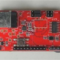
XR21V1410IL-0C-EB Exar Corporation, XR21V1410IL-0C-EB Datasheet - Page 4

XR21V1410IL-0C-EB
Manufacturer Part Number
XR21V1410IL-0C-EB
Description
Interface Modules & Development Tools For XR21V1410 QFN16 USB, RS485;No Cables
Manufacturer
Exar Corporation
Series
-r
Specifications of XR21V1410IL-0C-EB
Interface Type
RS-232, USB
Operating Supply Voltage
3.3 V
Product
Interface Modules
Silicon Core Number
XR21V1410
Application Sub Type
UART
Kit Contents
Board
Main Purpose
Interface, USB 2.0 to UART
Embedded
No
Utilized Ic / Part
XR21V1410IL
Primary Attributes
-
Secondary Attributes
-
Silicon Manufacturer
Exar
Kit Application Type
Communication & Networking
For Use With/related Products
XR21V1410
Lead Free Status / RoHS Status
Lead free / RoHS Compliant
XR21V1410
1-CH FULL-SPEED USB UART
N
Pin Description
USB Interface Signals
I
Miscellaneous Signals
2
OTE
C Interface Signals
LOWPOWER
: Pin type: I=Input, O=Output, I/O= Input/output, OD=Output Open Drain.
USBD+
USBD-
N
GND
SDA
VCC
SCL
AME
16-QFN
P
1, 13
15
14
12
16
IN
11
2
#
I/O OD
T
Pwr
Pwr
OD
I/O
I/O
YPE
O
Low power status output. This pin will be asserted whenever the V1410
device is placed into the suspend state.
This pin is sampled momentarily at power-up or at any USB bus reset to
configure the polarity of the LOWPOWER output during suspend mode.
An external (10K) pull-up resistor will cause the LOWPOWER pin to be
asserted HIGH during suspend mode. An external (3.3K) pull-down resis-
tor will cause the LOWPOWER pin to be asserted LOW during suspend
mode.
USB port differential data plus. This pin has a 1.5 K Ohm internal pull-up
resistor.
USB port differential data minus.
I
EEPROM can be used to store default configurations upon power-up
including the USB Vendor ID and Device ID. See
resistor (typically 4.7 to 10 KOhms) is required.
If an EEPROM is not used, this pin can be used with the SCL pin to
select the Remote Wake-up and Power modes. An external pull-up or
pull-down resistor is required. See
I
be used to store default configurations upon power-up including the USB
Vendor ID and Device ID. See
to 10 KOhms) is required.
If an EEPROM is not used, this pin can be used with the SDA pin to
select the Remote Wake-up and Power modes. An external pull-up or
pull-down resistor is required. See
+3.3V power supply. (Note that all device inputs are 5V tolerant.)
Power supply common, ground.
2
2
C-controller data input/output (open-drain). An optional external I
C-controller serial input clock. An optional external I
4
D
Table 3
ESCRIPTION
Table 2
Table 2
. A pull-up resistor (typically 4.7
Table 3
2
C EEPROM can
. A pull-up
REV. 1.2.0
2
C


