DLP-RF2-RELAY DLP Design Inc, DLP-RF2-RELAY Datasheet - Page 2
DLP-RF2-RELAY
Manufacturer Part Number
DLP-RF2-RELAY
Description
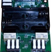
Zigbee / 802.15.4 Modules & Development Tools LATCHING RELAY BOARD FOR RF2 MODULE
Manufacturer
DLP Design Inc
Datasheet
1.DLP-RF2-RELAY.pdf
(3 pages)
Specifications of DLP-RF2-RELAY
Wireless Frequency
2.4 GHz
Operating Voltage
250 V
Lead Free Status / RoHS Status
Lead free / RoHS Compliant


DLP-RF2 board set will immediately enter the low-power mode drawing less than 40 microamps
of current from the two AA batteries. The RF2 module will wake up from the low-power mode
either periodically, based on a preset value in the setup of the DLP-RF2, or due to a change on
the door switch input. On wake up, the DLP-RF2 will attempt to check in with the system
controller. Once communications with the host controller are complete, the RF2 will return to
low-power mode.
Refer to the datasheet for the DLP-RF2 for additional details on the low-power mode.
Door Switch
Wiring terminal CN1 is provided on the DLP-RF2RELAY for connection to a set of normally
open or normally closed door switch contacts. When the door switch contacts are opened or
closed, the DLP-RF2 is brought out of sleep mode and a broadcast packet (destination ID=0) is
transmitted. The system controller transceiver (DLP-RF1 or DLP-RF2) responds to this packet
by requesting the battery voltage, and/or to set or reset on of the relays. The system controller
then has the option of instructing the DLP-RF2RELAY and DLP-RF2 board set to return
immediately to sleep.
Latching Relays
The two relays used are latching type relays and as such will only draw current from the
batteries when changing states. The process of changing states takes about 10 milliseconds
and requires a low-high-low pulse on one of 4 digital I/O lines from the DLP-RF2 transceiver.
To position relay K1 to the RESET position, pulse B3 high for 10mS.
To position relay K1 to the SET position, pulse B1 high for 10mS.
To position relay K2 to the RESET position, pulse B6 high for 10mS.
To position relay K2 to the SET position, pulse B5 high for 10mS.
If using the SIPP firmware in the DLP-RF2 as shipped from DLP Design, commands for these
features are provided.
The contact specifications are as follows (the contacts were connected in parallel to achieve
these ratings):
Contact Ratings: 120W, 250VA
Max Switching Voltage: 220VDC, 250 VAC
Max Switching Current: 4A
Max Carrying Current: 4A
Battery Power Measurement
The battery power measurement system works by placing a light load (approximately 10
milliamps) on the two AA batteries and then measuring the battery voltage using the A/D
converter in the DLP-RF2. A 2.1-volt voltage regulator is used as a voltage reference to set the
max voltage for the A/D converter in the DLP-RF2. The connection from the batteries to the A/D
converter is made via a voltage divider so that the battery voltage (~3.2V max) is within the
range of the 2.1-volt reference after being divided by 2.
DLP-RF2 DLP Design, Inc.
2
Rev 1.0 (January 2005)
Related parts for DLP-RF2-RELAY
Image
Part Number
Description
Manufacturer
Datasheet
Request
R

Part Number:
Description:
Zigbee / 802.15.4 Modules & Development Tools USE 626-DLP-RF2-Z
Manufacturer:
DLP Design Inc
Datasheet:

Part Number:
Description:
Industrial Humidity Sensors TEMP AND HUMIDITY SENSOR FOR RF2 MOD.
Manufacturer:
DLP Design Inc
Datasheet:
Part Number:
Description:
Zigbee / 802.15.4 Modules & Development Tools TTL SERIAL INTERFACE MODULE
Manufacturer:
DLP Design Inc
Datasheet:
Part Number:
Description:
Zigbee / 802.15.4 Modules & Development Tools TTL SERIAL INTERFACE MODULE
Manufacturer:
DLP Design Inc
Datasheet:

Part Number:
Description:
Zigbee / 802.15.4 Modules & Development Tools TTL SERIAL INTERFACE PROTO BOARD
Manufacturer:
DLP Design Inc
Datasheet:

Part Number:
Description:
MODULE DATA-ACQUISITION 8-CH
Manufacturer:
DLP Design Inc
Datasheet:

Part Number:
Description:
MODULE DATA-ACQUISITION 20-CH
Manufacturer:
DLP Design Inc
Datasheet:

Part Number:
Description:
RFID READER/WRITER SNGL-CH OEM
Manufacturer:
DLP Design Inc
Datasheet:

Part Number:
Description:
MODULE USB-MCU FT245RL W/16F877A
Manufacturer:
DLP Design Inc
Datasheet:

Part Number:
Description:
MODULE USB-TO-FPGA TRAINING TOOL
Manufacturer:
DLP Design Inc
Datasheet:

Part Number:
Description:
MODULE USB-MCU FT232R W/18F2410
Manufacturer:
DLP Design Inc
Datasheet:

Part Number:
Description:
MODULE USB-MCU FT245RL W/SX48
Manufacturer:
DLP Design Inc
Datasheet:

Part Number:
Description:
MODULE USB-MCU FT2232D W/16F877A
Manufacturer:
DLP Design Inc
Datasheet:

Part Number:
Description:
MODULE USB-TO-FPGA SPARTAN3
Manufacturer:
DLP Design Inc
Datasheet:

Part Number:
Description:
MOD USB-MCU FT245RL W/18LF8722
Manufacturer:
DLP Design Inc
Datasheet: