DLP-RF2-PROTO DLP Design Inc, DLP-RF2-PROTO Datasheet - Page 3
DLP-RF2-PROTO
Manufacturer Part Number
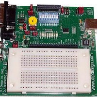
DLP-RF2-PROTO
Description
Zigbee / 802.15.4 Modules & Development Tools TTL SERIAL INTERFACE PROTO BOARD
Manufacturer
DLP Design Inc
Datasheet
1.DLP-RF2-PROTO.pdf
(5 pages)
Specifications of DLP-RF2-PROTO
Wireless Frequency
2.4 GHz
Interface Type
RS-232, USB
Operating Voltage
3 V
For Use With/related Products
MC9S08GT60
Lead Free Status / RoHS Status
Lead free / RoHS Compliant


The 8 LEDs indicate the current state of each digital I/O line and are buffered such that minimal current is
drawn from the microcontroller on the DLP-RF2. An inverting buffer is used so that when a digital I/O line
is high, the associated LED will be on. If developing a low-power design, the jumper at JP9 can be
removed so that power consumption is greatly reduced.
DB9 INTERFACE
The DLP-RF2PROTO provides a DB9 connector and level converter circuitry for connection to a legacy
RS232C device. This interface is provided to assist the developer in writing custom firmware and system
control software for instances where communication is required between the DLP-RF2 and a piece of
equipment that would normally connect to a host computer via RS232C.
Standard baud rates supported (limited by the DLP-RF2) are 2400, 4800, 9600 (default), 14400, 19200,
38400, 128000, and 250000 baud).
A jumper (JP10) is provided for removing power from the DB9 interface circuitry in the even the user is
developing a low-power device.
LOW POWER MODE JUMPER
Jumper JP6 can be used to hold port pin RX2/C1 low at power up of the DLP-RF2. If using the SIPP
firmware in the DLP-RF2 as shipped from DLP Design, on power up the RF2 will immediately enter the
low-power mode drawing less than 40 microamps of current at pin 12 of interface connector CN5. The
RF2 module will wake up periodically from the low-power mode and attempt to check in with the system
controller. Once communications with the host controller are complete, the RF2 will return to low-power
mode.
Several factors can prevent the RF2 from achieving the specified low-power current level of less than 40
microamps. Current draw from a digital I/O pin into user electronics, pulling low on a digital I/O line while
an internal pull-up in the microcontroller is enabled, or excessive activity on a monitored digital input are
three examples of items that should be avoided if attempting to minimize current.
Refer to the datasheet for the DLP-RF2 for additional details on the low-power mode of operation.
BDM HEADER
The BDM interface header is provided for making easy connection to the MC9S08GT60 microcontroller
on the DLP-RF2 transceiver for programming user provided custom firmware. Firmware programming
through the BDM interface requires the use of a device programmer (purchased separately).
CURRENT MONITOR JUMPERS
Jumpers JP1 and JP4 are provided for allowing the user to easily connect an ammeter and monitor either
the current drawn from the 3 volt regulator or the current drawn by the DLP-RF2 transceiver. Simply
remove the jumper and connect a current meter in series to make the measurement.
DLP-RF2PROTO DLP Design, Inc.
3
Rev 1.0 (March 2005)
Related parts for DLP-RF2-PROTO
Image
Part Number
Description
Manufacturer
Datasheet
Request
R

Part Number:
Description:
Zigbee / 802.15.4 Modules & Development Tools USE 626-DLP-RF2-Z
Manufacturer:
DLP Design Inc
Datasheet:

Part Number:
Description:
Zigbee / 802.15.4 Modules & Development Tools LATCHING RELAY BOARD FOR RF2 MODULE
Manufacturer:
DLP Design Inc
Datasheet:

Part Number:
Description:
Industrial Humidity Sensors TEMP AND HUMIDITY SENSOR FOR RF2 MOD.
Manufacturer:
DLP Design Inc
Datasheet:
Part Number:
Description:
Zigbee / 802.15.4 Modules & Development Tools TTL SERIAL INTERFACE MODULE
Manufacturer:
DLP Design Inc
Datasheet:
Part Number:
Description:
Zigbee / 802.15.4 Modules & Development Tools TTL SERIAL INTERFACE MODULE
Manufacturer:
DLP Design Inc
Datasheet:

Part Number:
Description:
MODULE DATA-ACQUISITION 8-CH
Manufacturer:
DLP Design Inc
Datasheet:

Part Number:
Description:
MODULE DATA-ACQUISITION 20-CH
Manufacturer:
DLP Design Inc
Datasheet:

Part Number:
Description:
RFID READER/WRITER SNGL-CH OEM
Manufacturer:
DLP Design Inc
Datasheet:

Part Number:
Description:
MODULE USB-MCU FT245RL W/16F877A
Manufacturer:
DLP Design Inc
Datasheet:

Part Number:
Description:
MODULE USB-TO-FPGA TRAINING TOOL
Manufacturer:
DLP Design Inc
Datasheet:

Part Number:
Description:
MODULE USB-MCU FT232R W/18F2410
Manufacturer:
DLP Design Inc
Datasheet:

Part Number:
Description:
MODULE USB-MCU FT245RL W/SX48
Manufacturer:
DLP Design Inc
Datasheet:

Part Number:
Description:
MODULE USB-MCU FT2232D W/16F877A
Manufacturer:
DLP Design Inc
Datasheet:

Part Number:
Description:
MODULE USB-TO-FPGA SPARTAN3
Manufacturer:
DLP Design Inc
Datasheet:

Part Number:
Description:
MOD USB-MCU FT245RL W/18LF8722
Manufacturer:
DLP Design Inc
Datasheet: