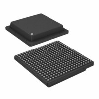
AD6635BB Analog Devices Inc, AD6635BB Datasheet - Page 25

AD6635BB
Manufacturer Part Number
AD6635BB
Description
IC,RF/Baseband Circuit,CMOS,BGA,324PIN,PLASTIC
Manufacturer
Analog Devices Inc
Series
AD6635r
Datasheet
1.AD6635BBPCB.pdf
(60 pages)
Specifications of AD6635BB
Rohs Status
RoHS non-compliant
Rf Type
Cellular, CDMA2000, EDGE, GPRS, GSM
Number Of Mixers
1
Current - Supply
880mA
Voltage - Supply
3 V ~ 3.6 V
Package / Case
324-BGA
Frequency
-
Gain
-
Noise Figure
-
Secondary Attributes
-
Lead Free Status / RoHS Status
Available stocks
Company
Part Number
Manufacturer
Quantity
Price
Part Number:
AD6635BB
Manufacturer:
ADI/亚德诺
Quantity:
20 000
Scaling with Floating-Point or Gain-Ranging ADCs
An example of the exponent control feature combines the
AD6600 and the AD6635. The AD6600 is an 11-bit ADC with
3 bits of gain ranging. In effect, the 11-bit ADC provides the
mantissa, and the 3 bits of relative signal strength indicator
(RSSI) for the exponent. Only five of the eight available steps
are used by the AD6600. See the AD6600 data sheet for addi-
tional details.
For gain-ranging ADCs such as the AD6600,
ExpInv = 1, ExpWeight = 0
where IN is the value of IN[13:0], Exp is the value of EXP[2:0],
and rCIC2 is the rCIC scale register value (0x92 bits 9-5 and 4-0).
“mod” is the remainder function. For example, mod(1,32) = 1,
mod(2,32) = 2, and mod(34,32) = 2.
The RSSI output of the AD6600 grows numerically with increas-
ing signal strength of the analog input (RSSI = 5 for a large
signal, RSSI = 0 for a small signal). When the Exponent Invert
Bit (ExpInv) is set to zero, the AD6635 will consider the small-
est signal at the IN[13:0] to be the largest, and as the EXP word
increases, it shifts the data down internally (EXP = 5 will shift a
14-bit word to the right by 5 internal bits before passing the
data to the rCIC2). In this example, if ExpInv = 0, the AD6635
regards the RSSI[2:0] = 5 as smallest signal and RSSI[2:0] = 0
as the largest signal possible on the AD6600. Thus, we can use
the Exponent Invert Bit to make the AD6635 exponent agree
with the AD6600 RSSI. Setting ExpInv = 1 forces the AD6635
to shift the data up (left) for growing EXP instead of down.
The exponent invert bit should always be set high for use
with the AD6600.
The Exponent Offset is used to shift the data up. For example,
Table I shows that with no rCIC2 scaling, 12 dB of range is
lost when the ADC input is at the largest level. This is not
desired because it lowers the dynamic range and SNR of the
system by reducing the signal of interest relative to the quan-
tization noise floor.
REV. 0
Figure 27. Typical Interconnection of the AD6645
Fixed-Point ADC and the AD6635
scaled input
_
(ExpOff = 0, ExpInv = 0)
AD6645
D11 (MSB)
D0 (LSB)
VDD
=
in
¥
2
IN13
IN2
IN1
IN0
EXP2
EXP1
EXP0
– mod( –
AD6635
7
Exp rCIC
IEN
+
2 32
,
)
–25–
ADC
Input
Level
Largest
Smallest
ExpInv = 1, rCIC2 Scale = 0)
To avoid this automatic attenuation of the full-scale ADC sig-
nal, the ExpOff is used to move the largest signal (RSSI = 5) up
to the point where there is no downshift. In other words, once
the Exponent Invert bit has been set, the Exponent Offset should
be adjusted so that mod(7-5 + ExpOff,32) = 0. This is the case
when Exponent Offset is set to 30 since mod(32,32) = 0. Table II
illustrates the use of ExpInv and ExpOff when used with the
AD6600 ADC.
ADC
Input
Level
Largest
Smallest
ExpInv = 1, ExpOff = 30, Exp Weight = 0)
This flexibility in handling the exponent allows the AD6635 to
interface with other gain-ranging ADCs besides the AD6600.
The Exponent Offset can be adjusted to allow up to seven
RSSI(EXP) ranges to be used as opposed to the AD6600’s five.
It also allows the AD6635 to be tailored in a system that employs
the AD6600 but does not utilize all of its signal range. For
example, if only the first four RSSI ranges are expected to
occur, then the ExpOff could be adjusted to 29, which would
make RSSI = 4 correspond to the 0 dB point of the AD6635.
Note that the above scale factor set in the rCIC2 register is only
to account for the ExpOff required. This register should also
account for compensating rCIC2 filter gain. The value required
for this will be given in the CIC2 filter section. Hence the final
value set in the rCIC2 register will be the sum total of ExpOff
and rCIC2 scale required.
Table II. AD6600 Transfer Function with
AD6620 ExpInv = 1, and ExpOff = 30
Table I. AD6600 Transfer Function with
AD6635 ExpInv = 1, and no ExpOff
101 (5)
000 (0)
101 (5)
000 (0)
AD6600
RSSI[2:0]
100 (4)
011 (3)
010 (2)
001 (1)
AD6600
RSSI[2:0]
100 (4)
011 (3)
010 (2)
001 (1)
AD6635
Data
/4 (>> 2)
/8 (>>3)
/16 (>> 4)
/32 (>> 5)
/64 (>> 6)
/128(>> 7)
AD6635
Data
/1 (>> 0)
/2 (>>1)
/4 (>> 2)
/8 (>> 3)
/16 (>> 4)
/32(>> 5)
AD6635
Signal
Reduction
(dB)
–12
–18
–24
–30
–36
–42
Signal
Reduction
(dB)
0
–6
–12
–18
–24
–30


