AD6635BB Analog Devices Inc, AD6635BB Datasheet - Page 37
AD6635BB
Manufacturer Part Number
AD6635BB
Description
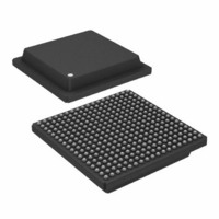
IC,RF/Baseband Circuit,CMOS,BGA,324PIN,PLASTIC
Manufacturer
Analog Devices Inc
Series
AD6635r
Datasheet
1.AD6635BBPCB.pdf
(60 pages)
Specifications of AD6635BB
Rohs Status
RoHS non-compliant
Rf Type
Cellular, CDMA2000, EDGE, GPRS, GSM
Number Of Mixers
1
Current - Supply
880mA
Voltage - Supply
3 V ~ 3.6 V
Package / Case
324-BGA
Frequency
-
Gain
-
Noise Figure
-
Secondary Attributes
-
Lead Free Status / RoHS Status
Available stocks
Company
Part Number
Manufacturer
Quantity
Price

Part Number:
AD6635BB
Manufacturer:
ADI/亚德诺
Quantity:
20 000


1. Set the appropriate channels to Sleep mode (a hard reset to
2. Note that the time from when the Sync pin goes high to
3. Write the Start Update Holdoff counter(s) (0x83) to the
4. Set the Start on Pin Sync bit and the appropriate Sync Pin
5. When the Sync pin is sampled high by the AD6635 CLK,
6. Unlike Soft Syncs, Pin Syncs have effect on all the channels at
Hop
Hop is a jump from one NCO frequency to a new NCO fre-
quency. This change in frequency can be synchronized via
microprocessor control (Soft Sync) or an external Sync signal
(Pin Sync) as described below.
To set the NCO frequency without synchronization, the follow-
ing method should be used.
Set Frequency No Hop
1. Set the NCO Freq Holdoff counter to 0.
2. Load the appropriate NCO frequency. The new frequency
Hop with Soft Sync
The AD6635 includes the ability to synchronize a change in
NCO frequency on multiple channels or chips under micropro-
cessor control. The NCO Freq Holdoff counter (0x84) in
conjunction with the Hop bit and the Sync bit (Ext address 4)
allow this synchronization. Basically, the NCO Freq Holdoff
counter delays the new frequency being loaded into the NCO
by its value (number of AD6635 CLKs). The following method
is used to synchronize a hop in frequency on multiple channels
via microprocessor control.
1. Note that the time from when the RDY (DTACK) pin goes
2. Write the NCO Freq Hold Off (0x84) counter to the appro-
3. Write the NCO Frequency register(s) to the new desired
4. Write the Hop bit and the Sync(s) bit high (Ext address 4).
5. This starts the NCO Freq Holdoff counter counting down.
REV. 0
the AD6635 RESET pin brings all four channels up in sleep
mode).
when the NCO begins processing data is the contents of the
Start Update Holdoff counter(s) (0x83) plus three master
clock cycles.
appropriate value (greater than 1 and less than 216 – 1). If
the chip(s) is not initialized, all other registers should be
loaded at this step.
Enable high (Ext address 4; A, B, C, or D).
this enables the countdown of the Start Update Holdoff
counter. The counter is clocked with the AD6635 CLK
signal. When it reaches a count of one, the Sleep bit of the
appropriate channel(s) is set low to activate the channel(s).
the same time. See Step 6 of the previous section, Start with
Soft Sync to understand the delays between the two sets of
channels. These delays do not occur with Pin Sync since the
Sync pins are shared between all the AD6635 channels.
will be immediately loaded to the NCO.
high to when the NCO begins processing data is the contents
of the NCO Freq Holdoff counter (0x84) plus seven master
clock cycles.
priate value (greater than 1 and less than 216 – 1).
frequency.
The counter is clocked with the AD6635 CLK signal. When
–37–
6. Note that channels 0 to 3 and 4 to 7 will receive syncs during
Hop with Pin Sync
The AD6635 includes four Sync pins to provide the most accu-
rate synchronization, especially between multiple AD6635s.
Synchronization of hopping to a new NCO frequency with an
external signal is accomplished with the following method.
1. Note that the time from when the SYNC pin goes high to
2. Write the NCO Freq Holdoff counter(s) (0x84) to the
3. Write the NCO Frequency register(s) to the new desired
4. Set the Hop on Pin Sync bit and the appropriate Sync Pin
5. When the selected Sync pin is sampled high by the AD6635
6. Unlike Soft Syncs, Pin Syncs have effect on all the channels
PARALLEL OUTPUT PORTS
The AD6635 incorporates four independent 16-bit parallel
ports and link ports for output data transfer. The parallel ports
and link ports share pins and internal mux circuitry. For each
data path, i.e., for each Output Port (A, B, C, or D), either a
parallel port or a link port can be selected, but not both. A
parallel port and a link port can be used simultaneously, but
only if they do not share the same data path; for example, Paral-
lel Port A along with Link Port B, or Parallel Port B with Link
Port A. Figure 34 illustrates a simplified block diagram showing
the AD6635’s output data routing configuration for one output
port. It also shows the shared pins; eight pins of AD6635 are
shared with link port data pins and the parallel port channel
indicator pins are shared with the link port clock in and clock
out pins.
it reaches a count of one, the new frequency is loaded into
the NCO.
different microport writes (separate syncs have to be used for
Channels 0 to 3 and 4 to 7). This time difference for the two
sets of channels (separate microport writes) should be noted.
when the NCO begins processing data is the contents of the
NCO Freq Holdoff counter (0x84) plus five master clock
cycles.
appropriate value (greater than 1 and less than 216 – 1).
frequency.
Enable high.
CLK, this enables the countdown of the NCO Freq Holdoff
counter. The counter is clocked with the AD6635 CLK
signal. When it reaches a count of one, the new frequency is
loaded into the NCO.
at the same time. See Step 6 of the section, Start with Soft
Sync, to understand the delays between the two sets of chan-
nels. These delays do not occur with Pin Sync since all the
Sync pins are shared between all the AD6635 channels.
AD6635
Related parts for AD6635BB
Image
Part Number
Description
Manufacturer
Datasheet
Request
R

Part Number:
Description:
±1.7g Dual-Axis IMEMS Accelerometer Evaluation Board
Manufacturer:
Analog Devices Inc
Datasheet:

Part Number:
Description:
Inertial Sensor Evaluation System
Manufacturer:
Analog Devices Inc
Datasheet:
Part Number:
Description:
Manufacturer:
Analog Devices Inc
Datasheet:
Part Number:
Description:
Manufacturer:
Analog Devices Inc
Datasheet:
Part Number:
Description:
Manufacturer:
Analog Devices Inc
Datasheet:
Part Number:
Description:
Manufacturer:
Analog Devices Inc
Datasheet:
Part Number:
Description:
Manufacturer:
Analog Devices Inc
Datasheet:
Part Number:
Description:
Manufacturer:
Analog Devices Inc
Datasheet:
Part Number:
Description:
Manufacturer:
Analog Devices Inc
Datasheet:
Part Number:
Description:
Manufacturer:
Analog Devices Inc
Datasheet:
Part Number:
Description:
Manufacturer:
Analog Devices Inc
Datasheet:
Part Number:
Description:
Manufacturer:
Analog Devices Inc
Datasheet:
Part Number:
Description:
Manufacturer:
Analog Devices Inc
Datasheet: