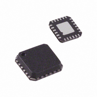
AD7147ACPZ-1REEL Analog Devices Inc, AD7147ACPZ-1REEL Datasheet - Page 17

AD7147ACPZ-1REEL
Manufacturer Part Number
AD7147ACPZ-1REEL
Description
IC,Converter, Other/Special/Miscellaneous,LLCC,24PIN
Manufacturer
Analog Devices Inc
Series
CapTouch™r
Type
Capacitive Sensor Controllerr
Datasheet
1.AD7147ACPZ-1500RL7.pdf
(72 pages)
Specifications of AD7147ACPZ-1REEL
Resolution (bits)
16 b
Data Interface
I²C, Serial
Voltage Supply Source
Single Supply
Voltage - Supply
2.6 V ~ 3.6 V
Operating Temperature
-40°C ~ 85°C
Mounting Type
Surface Mount
Package / Case
24-LFCSP
Lead Free Status / RoHS Status
Lead free / RoHS Compliant
For Use With
EVAL-AD7147EBZ - BOARD EVAL FOR AD7147ACPZEVAL-AD7147-1EBZ - BOARD EVAL FOR AD7147ACPZ-1
Sampling Rate (per Second)
-
Lead Free Status / RoHS Status
Lead free / RoHS Compliant
CAPACITANCE SENSOR INPUT CONFIGURATION
Each input connection from the external capacitance sensors to
the converter of the AD7147 can be uniquely configured by
using the registers in Bank 2 (see Table 38). These registers are
used to configure the input pin connection setups, sensor offsets,
sensor sensitivities, and sensor limits for each stage. Each sensor
can be individually optimized. For example, a button sensor
connected to STAGE0 can have different sensitivity and offset
values than a button with another function that is connected to a
different stage.
CINx INPUT MULTIPLEXER SETUP
Table 34 and Table 35 list the available options for the
CINx_CONNECTION_SETUP bits when the sensor input
pins are connected to the CDC.
The AD7147 has an on-chip multiplexer that routes the input
signals from each CINx pin to the input of the converter. Each
input pin can be tied to either the negative or positive input of
the CDC, or it can be left floating. Each input can also be
internally connected to the BIAS signal to help prevent cross
coupling. If an input is not used, always connect it to the BIAS.
Connecting a CINx input pin to the positive CDC input results
in an increase in CDC output code when the corresponding
sensor is activated. Connecting a CINx input pin to the negative
CDC input results in a decrease in CDC output code when the
corresponding sensor is activated.
The AD7147 performs a sequence of 12 conversions. The multi-
plexer can have different settings for each of the 12 conversions.
For example, CIN0 is connected to the negative CDC input for
conversion STAGE1, left floating for conversion STAGE1, and
so on, for all 12 conversion stages.
For each CINx input for each conversion stage, two bits control
how the input is connected to the converter, as shown in Figure 29.
Examples
To connect CIN3 to the positive CDC input on Stage 0 use the
following setting:
STAGE0_CONNECTION[6:0] = 0xFFBF
STAGE0_CONNECTION[12:7] = 0x2FFF
CIN10
CIN11
CIN12
CIN0
CIN1
CIN2
CIN3
CIN4
CIN5
CIN6
CIN7
CIN8
CIN9
CIN CONNECTION SETUP BITS
Figure 29. Input Mux Configuration Options
00
01
10
11
Rev. B | Page 17 of 72
CIN SETTING
CINx FLOATING
CINx CONNECTED TO
NEGATIVE CDC INPUT
CINx CONNECTED TO
POSITIVE CDC INPUT
CINx CONNECTED TO
BIAS
To connect CIN0 to the positive CDC input and CIN12 to the
negative CIN input on Stage 5 use the following settings:
STAGE5_CONNECTION[6:0] = 0xFFFE
STAGE5_CONNECTION[12:7] = 0x37FF
SINGLE-ENDED CONNECTIONS TO THE CDC
A single-ended connection to the CDC is defined as one CINx
input connected to either the positive or negative CDC input
for one conversion stage. A differential connection to the CDC is
defined as one CINx input connected to the positive CDC input
and a second CINx input connected to the negative input of the
CDC for one conversion stage.
For any stage, if a single-ended connection to the CDC is made
in that stage, the SE_CONNECTION_SETUP bits (Bits[13:12] in
the STAGEx_CONNECTION[12:7] register) should be applied as
follows:
•
•
•
•
These bits ensure that during a single-ended connection to the
CDC, the input paths to both CDC terminals are matched,
which in turn improves the power-supply rejection of the
converter measurement.
These bits should be applied in addition to setting the other bits
in the STAGEx_CONNECTION registers, as outlined in the
CINx Input Multiplexer Setup section.
If more than one CINx input is connected to either the positive
or negative input of the converter for the same conversion, set
SE_CONNECTION_SETUP to 11. For example, if CIN0 and
CIN3 are connected to the positive input of the CDC, set
SE_CONNECTION_SETUP to 11.
SE_CONNECTION_SETUP = 00: do not use.
SE_CONNECTION_SETUP = 01: single-ended connection.
For this stage, there is one CINx connected to the positive
CDC input.
SE_CONNECTION_SETUP = 10: single-ended connection.
For this stage, there is one CINx connected to the negative
CDC input.
SE_CONNECTION_SETUP = 11: differential connection.
For this stage, there is one CINx connected to the nega
tive CDC input and one CINx connected to the positive
CDC input.
+
–
CDC
AD7147


