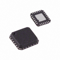
AD7147PACPZ-1RL Analog Devices Inc, AD7147PACPZ-1RL Datasheet - Page 12

AD7147PACPZ-1RL
Manufacturer Part Number
AD7147PACPZ-1RL
Description
CAPACITANCE TO DIGITAL CONVERTER
Manufacturer
Analog Devices Inc
Series
CapTouch™r
Type
Capacitive Sensor Controllerr
Datasheet
1.AD7147ACPZ-1500RL7.pdf
(72 pages)
Specifications of AD7147PACPZ-1RL
Resolution (bits)
16 b
Data Interface
I²C, Serial
Voltage Supply Source
Single Supply
Voltage - Supply
2.6 V ~ 3.6 V
Operating Temperature
-40°C ~ 85°C
Mounting Type
Surface Mount
Package / Case
24-LFCSP
Lead Free Status / RoHS Status
Lead free / RoHS Compliant
Sampling Rate (per Second)
-
Lead Free Status / Rohs Status
Compliant
AD7147
Registering a Sensor Activation
When a user approaches a sensor, the total capacitance associated
with that sensor changes and is measured by the AD7147. If
the change causes a set threshold to be exceeded, the AD7147
interprets this as a sensor activation.
On-chip threshold limits are used to determine when a sensor
activation occurs. Figure 20 shows the change in CDC_RESULT_Sx
when a user activates a sensor. The sensor is deemed to be active
only when the value of CDC_RESULT_Sx is either greater than the
value of STAGEx_HIGH_THRESHOLD or less than the value
of STAGEx_LOW_THRESHOLD.
In Figure 20, two sensor activations are shown. Sensor Active A
occurs when a sensor is connected to the positive input of the
converter. In this case, when a user activates the sensor, there is an
increase in CDC code, and the value of CDC_RESULT_Sx exceeds
that of STAGEx_HIGH_THRESHOLD. Sensor Active B occurs
when the sensor is connected to the negative input of the converter.
In this case, when a user activates the sensor, there is a decrease
in CDC code, and the value of CDC_RESULT_Sx becomes less
than the value of STAGEx_LOW_THRESHOLD.
For each conversion stage, the STAGEx_HIGH_THRESHOLD
and STAGEx_LOW_THRESHOLD registers are in Register
Bank 3. The values in these registers are updated automatically
by the AD7147 due to its environmental calibration and
adaptive threshold logic.
At power-up, the values in the STAGEx_HIGH_THRESHOLD
and STAGEx_LOW_THRESHOLD registers are the same as those
in the STAGEx_OFFSET_HIGH and STAGEx_OFFSET_LOW
registers in Bank 2. The user must program the STAGEx_OFFSET
_HIGH and STAGEx_OFFSET_LOW registers on device power-
up. See the Environmental Calibration section of the data sheet
for more information.
SENSOR ACTIVE (A)
Figure 20. Sensor Activation Thresholds
SENSOR ACTIVE (B)
CDC_RESULT_Sx
STAGEx_HIGH_THRESHOLD
AMBIENT OR
NO-TOUCH VALUE
STAGEx_LOW_THRESHOLD
Rev. B | Page 12 of 72
Complete Solution for Capacitance Sensing
Analog Devices, Inc., provides a complete solution for
capacitance sensing. The two main elements to the solution are
the sensor PCB and the AD7147.
If the application requires high resolution sensors such as scroll
bars or wheels, software is required that runs on the host
processor. The memory requirements for the host depend on
the sensor and are typically 10 kB of code and 600 bytes of data
memory, depending on the sensor type.
Analog Devices supplies the sensor PCB footprint design
libraries to the customer and supplies any necessary software on
an open source basis.
BIAS PIN
This pin is connected internally to a bias node of the AD7147.
To ensure correct operation of the AD7147, connect a 100 nF
capacitor between the BIAS pin and ground. The voltage seen at
the BIAS pin is V
OPERATING MODES
The AD7147 has three operating modes. Full power mode, where
the device is always fully powered, is suited for applications where
power is not a concern (for example, game consoles that have an
ac power supply). Low power mode, where the part automatically
powers down when no sensor is active, is tailored to provide
significant power savings compared with full power mode and
is suited for mobile applications, where power must be
conserved. In shutdown mode, the part shuts down completely.
The POWER_MODE bits (Bit 0 and Bit 1) of the control
register set the operating mode on the AD7147. The control
register is at Address 0x000. Table 8 shows the POWER_MODE
settings for each operating mode. To put the AD7147 into
shutdown mode, set the POWER_MODE bits to either 01 or 11.
Table 8. POWER_MODE Settings
POWER_MODE Bits
00
01
10
11
The power-on default setting of the POWER_MODE bits is 00,
full power mode.
SENSOR PCB
Figure 21. Three-Part Capacitance Sensing Solution
CC
/2.
AD7147
Operating Mode
Full power mode
Shutdown mode
Low power mode
Shutdown mode
SPI OR I
2
C
HOST PROCESSOR
600 BYTES RAM
10kB ROM
1 MIPS


