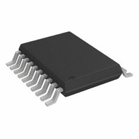
AD9834BRU Analog Devices Inc, AD9834BRU Datasheet - Page 29

AD9834BRU
Manufacturer Part Number
AD9834BRU
Description
10 Bit, 20 Pin DDS I.C.
Manufacturer
Analog Devices Inc
Datasheet
1.AD9834BRUZ.pdf
(36 pages)
Specifications of AD9834BRU
Rohs Status
RoHS non-compliant
Design Resources
Amplitude Control Circuit for AD9834 Waveform Generator (CN0156)
Resolution (bits)
10 b
Master Fclk
50MHz
Tuning Word Width (bits)
28 b
Voltage - Supply
2.3 V ~ 5.5 V
Operating Temperature
-40°C ~ 105°C
Mounting Type
Surface Mount
Package / Case
20-TSSOP
Lead Free Status / RoHS Status
Contains lead / RoHS non-compliant
For Use With
EVAL-AD9834EBZ - BOARD EVAL FOR AD9834
Lead Free Status / RoHS Status
Contains lead / RoHS non-compliant
Available stocks
Company
Part Number
Manufacturer
Quantity
Price
Part Number:
AD9834BRU
Manufacturer:
ADI/亚德诺
Quantity:
20 000
Part Number:
AD9834BRUZ
Manufacturer:
ADI/亚德诺
Quantity:
20 000
Company:
Part Number:
AD9834BRUZ-REEL
Manufacturer:
AD
Quantity:
1 045
Part Number:
AD9834BRUZ-REEL
Manufacturer:
ADI/亚德诺
Quantity:
20 000
EVALUATION BOARD
SYSTEM DEVELOPMENT PLATFORM
The system development platform (SDP) is a hardware and
software evaluation tool for use in conjunction with product
evaluation boards. The SDP board is based on the Black fin ® BF527
processor with USB connectivity to the PC through a USB 2.0 high
speed port. For more information about this device, go to:
www.analog.com/en/embedded-processing-
dsp/blackfin/bf527sdp-hw/processors/product.html.
Note that the SDP board is sold separately from the AD9834
evaluation board.
AD9834 TO SPORT INTERFACE
The Analog Devices SDP board has a SPORT serial port that is
used to control the serial inputs to the AD9834 . The connections
are shown in Figure 39.
The AD9834 evaluation board allows designers to evaluate the high
performance AD9834 DDS modulator with a minimum of effort.
The GUI interface for the AD9834 evaluation board is shown in
Figure 40.
ADSP-BF527
SPORT_TSCLK
SPORT_DTO
SPORT_TFS
Figure 39. SDP to AD9834 Interface
FSYNC
SCLK
SDATA
AD9834
Rev. C | Page 29 of 36
The DDS evaluation kit includes a populated, tested AD9834
PCB. Software is available with the evaluation board that allows
the user to easily program the AD9834. The schematics of the
AD9834 evaluation board are shown in Figure 41 and Figure 42.
The software runs on any IBM-compatible PC that has Microsoft®
Windows® 95, Windows 98, Windows ME, Windows 2000 NT®,
or Windows 7 installed.
Additional details can be found in the EVAL-AD9834EB data
sheet that is available on the software CD and the AD9834
product page.
XO vs. EXTERNAL CLOCK
The AD9834 can operate with master clocks up to 75 MHz. A
75 MHz general oscillator is included on the evaluation board.
However, this oscillator can be removed and, if required, an
external CMOS clock can be connected to the part.
Two options for the general oscillator are:
•
•
POWER SUPPLY
Power to the AD9834 evaluation board can be provided from
USB connector or externally through pin connections. The
power leads should be twisted to reduce ground loops.
AEL 301 series crystals oscillators, AEL Crystals, Ltd.
SG-310SCN oscillators, Epson Toyocom Corporation
Figure 40. AD9834 Evaluation Software
AD9834


