ADG333ABN Analog Devices Inc, ADG333ABN Datasheet - Page 11
ADG333ABN
Manufacturer Part Number
ADG333ABN
Description
Multiplexer IC
Manufacturer
Analog Devices Inc
Type
Analog Switchr
Datasheet
1.ADG333ABRZ.pdf
(12 pages)
Specifications of ADG333ABN
Peak Reflow Compatible (260 C)
No
Leakage Current
0.1nA
No. Of Circuits
4
Leaded Process Compatible
No
Mounting Type
Through Hole
No. Of Channels
4
On Resistance Rds(on)
20mohm
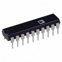
Package / Case
20-DIP
Rohs Status
RoHS non-compliant
Function
Switch
Circuit
4 x SPDT
On-state Resistance
45 Ohm
Voltage Supply Source
Single Supply
Voltage - Supply, Single/dual (±)
12V
Current - Supply
0.01µA
Operating Temperature
-40°C ~ 85°C
Package
20PDIP N
Maximum On Resistance
45@±15V Ohm
Maximum High Level Output Current
20 mA
Maximum Turn-off Time
100(Typ)@12V ns
Maximum Turn-on Time
110(Typ)@12V ns
Switch Architecture
SPDT
Power Supply Type
Single|Dual
Lead Free Status / RoHS Status
Contains lead / RoHS non-compliant
Available stocks
Company
Part Number
Manufacturer
Quantity
Price
Company:

Part Number:
ADG333ABN
Manufacturer:
Analog Devices Inc.
Quantity:
1 050
Part Number:
ADG333ABNZ
Manufacturer:
ADI/亚德诺
Quantity:
20 000


APPLICATION INFORMATION
ADG333A SUPPLY VOLTAGES
The ADG333A can operate from a dual or signal supply. V
should be connected to GND when operating with a single
supply. When using a dual supply, the ADG333A can also
operate with unbalanced supplies; for example V
V
exceed 30 V, V
to V
the ADG333A supply voltage directly affects the input signal
range, the switch on resistance and the switching times of the
part. The effects of the power supplies on these characteristics
can be clearly seen from the Typical Performance Characteristics
curves.
SS
= −5 V. The only restrictions are that V
SS
must not exceed +44 V. It is important to remember that
SS
to GND must not drop below −30 V, and V
DD
to GND must not
DD
= 20 V and
SS
DD
Rev. A | Page 11 of 12
POWER SUPPLY SEQUENCING
When using CMOS devices, care must be taken to ensure
correct power-supply sequencing. Incorrect power-supply
sequencing can result in the device being subjected to stresses
beyond those listed in the Absolute Maximum Ratings. This is
also true for the ADG333A. Always turn on V
by V
mum specified ratings can then be safely presented to the source
or drain of the switch
SS
and the logic signals. An external signal within the maxi-
DD
first, followed
ADG333A
Related parts for ADG333ABN
Image
Part Number
Description
Manufacturer
Datasheet
Request
R

Part Number:
Description:
±1.7g Dual-Axis IMEMS Accelerometer Evaluation Board
Manufacturer:
Analog Devices Inc
Datasheet:

Part Number:
Description:
Inertial Sensor Evaluation System
Manufacturer:
Analog Devices Inc
Datasheet:
Part Number:
Description:
Manufacturer:
Analog Devices Inc
Datasheet:
Part Number:
Description:
Manufacturer:
Analog Devices Inc
Datasheet:
Part Number:
Description:
Manufacturer:
Analog Devices Inc
Datasheet:
Part Number:
Description:
Manufacturer:
Analog Devices Inc
Datasheet:
Part Number:
Description:
Manufacturer:
Analog Devices Inc
Datasheet:
Part Number:
Description:
Manufacturer:
Analog Devices Inc
Datasheet:
Part Number:
Description:
Manufacturer:
Analog Devices Inc
Datasheet:
Part Number:
Description:
Manufacturer:
Analog Devices Inc
Datasheet:
Part Number:
Description:
Manufacturer:
Analog Devices Inc
Datasheet:
Part Number:
Description:
Manufacturer:
Analog Devices Inc
Datasheet:
Part Number:
Description:
Manufacturer:
Analog Devices Inc
Datasheet: