ADG333ABN Analog Devices Inc, ADG333ABN Datasheet - Page 6
ADG333ABN
Manufacturer Part Number
ADG333ABN
Description
Multiplexer IC
Manufacturer
Analog Devices Inc
Type
Analog Switchr
Datasheet
1.ADG333ABRZ.pdf
(12 pages)
Specifications of ADG333ABN
Peak Reflow Compatible (260 C)
No
Leakage Current
0.1nA
No. Of Circuits
4
Leaded Process Compatible
No
Mounting Type
Through Hole
No. Of Channels
4
On Resistance Rds(on)
20mohm
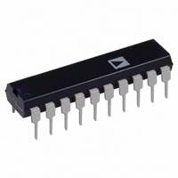
Package / Case
20-DIP
Rohs Status
RoHS non-compliant
Function
Switch
Circuit
4 x SPDT
On-state Resistance
45 Ohm
Voltage Supply Source
Single Supply
Voltage - Supply, Single/dual (±)
12V
Current - Supply
0.01µA
Operating Temperature
-40°C ~ 85°C
Package
20PDIP N
Maximum On Resistance
45@±15V Ohm
Maximum High Level Output Current
20 mA
Maximum Turn-off Time
100(Typ)@12V ns
Maximum Turn-on Time
110(Typ)@12V ns
Switch Architecture
SPDT
Power Supply Type
Single|Dual
Lead Free Status / RoHS Status
Contains lead / RoHS non-compliant
Available stocks
Company
Part Number
Manufacturer
Quantity
Price
Company:

Part Number:
ADG333ABN
Manufacturer:
Analog Devices Inc.
Quantity:
1 050
Part Number:
ADG333ABNZ
Manufacturer:
ADI/亚德诺
Quantity:
20 000


ADG333A
TERMINOLOGY
R
Ohmic resistance between D and S.
∆R
R
constant load current.
R
Difference between the R
I
Source leakage current with the switch off.
I
Drain leakage current with the switch off.
I
Channel leakage current with the switch on.
V
Analog voltage on Terminals D, S.
C
OFF switch source capacitance.
C
OFF switch drain capacitance.
C
ON switch capacitance.
S
D
D
ON
ON
ON
S
D
D
D
, I
(OFF)
(OFF)
, C
(OFF)
ON
(V
(OFF)
Match
S
variation due to a change in the analog input voltage with a
(ON)
S
S
)
(ON)
ON
of any two channels.
Rev. A | Page 6 of 12
t
Delay between applying the digital control input and the output
switching on.
t
Delay between applying the digital control input and the output
switching off.
t
Break-before-make delay when switches are configured as a
multiplexer.
V
Maximum input voltage for Logic 0.
V
Minimum input voltage for Logic 1.
I
Input current of the digital input.
Crosstalk
A measure of unwanted signal which is coupled through from
one channel to another as a result of parasitic capacitance.
Off Isolation
A measure of unwanted signal coupling through an OFF switch.
Charge Injection
A measure of the glitch impulse transferred from the digital
input to the analog output during switching.
ON
OFF
OPEN
INL
INL
INH
(I
INH
)
Related parts for ADG333ABN
Image
Part Number
Description
Manufacturer
Datasheet
Request
R

Part Number:
Description:
±1.7g Dual-Axis IMEMS Accelerometer Evaluation Board
Manufacturer:
Analog Devices Inc
Datasheet:

Part Number:
Description:
Inertial Sensor Evaluation System
Manufacturer:
Analog Devices Inc
Datasheet:
Part Number:
Description:
Manufacturer:
Analog Devices Inc
Datasheet:
Part Number:
Description:
Manufacturer:
Analog Devices Inc
Datasheet:
Part Number:
Description:
Manufacturer:
Analog Devices Inc
Datasheet:
Part Number:
Description:
Manufacturer:
Analog Devices Inc
Datasheet:
Part Number:
Description:
Manufacturer:
Analog Devices Inc
Datasheet:
Part Number:
Description:
Manufacturer:
Analog Devices Inc
Datasheet:
Part Number:
Description:
Manufacturer:
Analog Devices Inc
Datasheet:
Part Number:
Description:
Manufacturer:
Analog Devices Inc
Datasheet:
Part Number:
Description:
Manufacturer:
Analog Devices Inc
Datasheet:
Part Number:
Description:
Manufacturer:
Analog Devices Inc
Datasheet:
Part Number:
Description:
Manufacturer:
Analog Devices Inc
Datasheet: