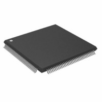
ADSP-2191MBSTZ-140 Analog Devices Inc, ADSP-2191MBSTZ-140 Datasheet - Page 25

ADSP-2191MBSTZ-140
Manufacturer Part Number
ADSP-2191MBSTZ-140
Description
IC,DSP,16-BIT,CMOS,QFP,144PIN,PLASTIC
Manufacturer
Analog Devices Inc
Series
ADSP-21xxr
Type
Fixed Pointr
Specifications of ADSP-2191MBSTZ-140
Interface
Host Interface, SPI, SSP, UART
Clock Rate
140MHz
Non-volatile Memory
External
On-chip Ram
160kB
Voltage - I/o
3.00V, 3.30V
Voltage - Core
2.50V
Operating Temperature
-40°C ~ 85°C
Mounting Type
Surface Mount
Package / Case
144-LQFP
Device Core Size
16b
Clock Freq (max)
140MHz
Mips
140
Device Input Clock Speed
140MHz
Ram Size
160KB
Operating Supply Voltage (typ)
2.5/3.3V
Operating Supply Voltage (min)
2.37/2.97V
Operating Supply Voltage (max)
2.63/3.6V
Operating Temp Range
-40C to 85C
Operating Temperature Classification
Industrial
Mounting
Surface Mount
Pin Count
144
Package Type
LQFP
Lead Free Status / RoHS Status
Lead free / RoHS Compliant
Lead Free Status / RoHS Status
Lead free / RoHS Compliant
Other names
ADSP-2191MBSTZ140
Available stocks
Company
Part Number
Manufacturer
Quantity
Price
Company:
Part Number:
ADSP-2191MBSTZ-140
Manufacturer:
MAXIM
Quantity:
101
Company:
Part Number:
ADSP-2191MBSTZ-140
Manufacturer:
Analog Devices Inc
Quantity:
10 000
Host Port ALE Mode Write Cycle Timing
Table 15
Address Latch Enable (ALE) mode. For more information on
ACK, Ready, ALE, and ACC mode selection, see the Host port
modes description
Table 15. Host Port ALE Mode Write Cycle Timing
1
2
REV. A
t
Measurement is for the second, third, or fourth byte of a host write transaction. The quantity of bytes to complete a host write transaction is dependent on
NH
Parameter
Switching Characteristics
t
t
t
t
t
Timing Requirements
t
t
t
t
t
t
t
t
t
t
t
at the same time.
the data bus size (8 or 16 bits) and the data type (16 or 24 bits).
WHKS1
WHKS2
WHKH
WHS
WHH
CSAL
ALPW
ALCSW
WCSW
ALW
WCS
HKWD
AALS
ALAH
DWS
WDH
are peripheral bus latencies (n t
and
Figure 14
HWR Asserted to HACK Asserted (Setup, ACK Mode) First
Byte
HWR Asserted to HACK Asserted (Setup, ACK Mode)
HWR Deasserted to HACK Deasserted (Hold, ACK Mode)
HWR Asserted to HACK Asserted (Setup, Ready Mode)
HWR Asserted to HACK Deasserted (Hold, Ready Mode)
First Byte
HCMS or HCIOMS Asserted to HALE Asserted
HALE Asserted Pulsewidth
HALE Deasserted to HCMS or HCIOMS Deasserted
HWR Deasserted to HCMS or HCIOMS Deasserted
HALE Deasserted to HWR Asserted
HWR Deasserted (After Last Byte) to HCMS or
HCIOMS Deasserted (Ready for Next Write)
HACK Asserted to HWR Deasserted (Hold, ACK Mode)
Address Valid to HALE Deasserted (Setup)
HALE Deasserted to Address Invalid (Hold)
Data Valid to HWR Deasserted (Setup)
HWR Deasserted to Data Invalid (Hold)
on Page
describe Host port write operations in
8.
HCLK
); these are internal DSP latencies related to the number of peripheral DMAs attempting to access DSP memory
–25–
2
Min
10
0
0
4
1
0
1
0
1.5
2
4
4
1
ADSP-2191M
Max
5t
10
10
10
5t
HCLK
HCLK
+t
+t
NH
NH
1
1
Unit
ns
ns
ns
ns
ns
ns
ns
ns
ns
ns
ns
ns
ns
ns
ns
ns


