CYWUSB6935-48LTXC Cypress Semiconductor Corp, CYWUSB6935-48LTXC Datasheet - Page 4
CYWUSB6935-48LTXC
Manufacturer Part Number
CYWUSB6935-48LTXC
Description
CYWUSB6935-48LTXC
Manufacturer
Cypress Semiconductor Corp
Specifications of CYWUSB6935-48LTXC
Frequency
2.4GHz
Data Rate - Maximum
62.5kbps
Modulation Or Protocol
DSSS, GFSK
Applications
AMR, ISM, RKE
Power - Output
0dBm
Sensitivity
-95dBm
Voltage - Supply
2.7 V ~ 3.6 V
Current - Receiving
57.7mA
Current - Transmitting
69.1mA
Data Interface
PCB, Surface Mount
Antenna Connector
PCB, Surface Mount
Operating Temperature
0°C ~ 70°C
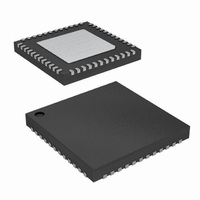
Package / Case
48-VQFN Exposed Pad, 48-HVQFN, 48-SQFN, 48-DHVQFN
Operating Temperature (min)
-40C
Operating Temperature (max)
85C
Operating Temperature Classification
Industrial
Product Depth (mm)
7mm
Product Length (mm)
7mm
Operating Supply Voltage (min)
2.7V
Operating Supply Voltage (typ)
3V
Operating Supply Voltage (max)
3.6V
Lead Free Status / RoHS Status
Lead free / RoHS Compliant
Memory Size
-
Lead Free Status / Rohs Status
Compliant
Available stocks
Company
Part Number
Manufacturer
Quantity
Price
Company:

Part Number:
CYWUSB6935-48LTXC
Manufacturer:
ST
Quantity:
1 200


Serializer/Deserializer (SERDES)
CYWUSB6935
(SERDES), which provides byte-level framing of transmit and
receive data. Bytes for transmission are loaded into the SERDES
and receive bytes are read from the SERDES via the SPI
interface. The SERDES provides double buffering of transmit
and receive data. While one byte is being transmitted by the
radio the next byte can be written to the SERDES data register
insuring there are no breaks in transmitted data.
After a receive byte has been received it is loaded into the
SERDES data register and can be read at any time until the next
byte is received, at which time the old contents of the SERDES
data register will be overwritten.
Application Interfaces
CYWUSB6935 has a fully synchronous SPI slave interface for
connectivity to the application MCU. Configuration and
byte-oriented data transfer can be performed over this interface.
An interrupt is provided to trigger real time events.
An optional SERDES Bypass mode (DIO) is provided for appli-
cations that require a synchronous serial bit-oriented data path.
This interface is for data only.
Clocking and Power Management
A 13-MHz crystal is directly connected to X13IN and X13 without
the need for external capacitors. The CYWUSB6935 has a
programmable trim capability for adjusting the on-chip load
capacitance supplied to the crystal.
Below are the requirements for the crystal to be directly
connected to X13IN and X13:
■
■
■
■
■
■
■
The radio frequency (RF) circuitry has on-chip decoupling capac-
itors. The CYWUSB6935 is powered from a 2.7-V to 3.6-V DC
supply. The CYWUSB6935 can be shut down to a fully static
state using the PD pin.
Receive Signal Strength Indicator (RSSI)
The RSSI register (Reg 0x22) returns the relative signal strength
of the ON-channel signal power and can be used to:
The internal RSSI voltage is sampled through a 5-bit
analog-to-digital converter (ADC). A state machine controls the
conversion process. Under normal conditions, the RSSI state
machine initiates a conversion when an ON-channel carrier is
detected and remains above the noise floor for over 50 μs. The
conversion produces a 5-bit value in the RSSI register (Reg
0x22, bits 4:0) along with a valid bit, RSSI register (Reg 0x22, bit
5). The state machine then remains in HALT mode and does not
Document Number : 38-16008 Rev. *G
1. Determine the connection quality
2. Determine the value of the noise floor
3. Check for a quiet channel before transmitting.
Nominal frequency: 13 MHz
Operating mode: Fundamental mode
Resonance mode: Parallel resonant
Frequency stability: ±30 ppm
Series resistance: <100 ohms
Load capacitance: 10 pF
Drive level: 10 μW to 100 μW
provides
a
data
Serializer/Deserializer
reset for a new conversion until the receive mode is toggled off
and on. After a connection has been established, the RSSI
register can be read to determine the relative connection quality
of the channel. A RSSI register value lower than 10 indicates that
the received signal strength is low, a value greater than 28
indicates a strong signal level.
To check for a quiet channel before transmitting, first set up
receive mode properly and read the RSSI register (Reg 0x22). If
the valid bit is zero, then force the Carrier Detect register (Reg
0x2F, bit 7=1) to initiate an ADC conversion. Then, wait greater
than 50 μs and read the RSSI register again. Next, clear the
Carrier Detect Register (Reg 0x2F, bit 7=0) and turn the receiver
OFF. Measuring the noise floor of a quiet channel is inherently a
'noisy' process so, for best results, this procedure should be
repeated several times (~20) to compute an average noise floor
level. A RSSI register value of 0-10 indicates a channel that is
relatively quiet. A RSSI register value greater than 10 indicates
the channel is probably being used. A RSSI register value
greater than 28 indicates the presence of a strong signal.
Application Interfaces
SPI Interface
The CYWUSB6935 has a four-wire SPI communication interface
between an application MCU and one or more slave devices.
The SPI interface supports single-byte and multi-byte serial
transfers. The four-wire SPI communications interface consists
of Master Out-Slave In (MOSI), Master In-Slave Out (MISO),
Serial Clock (SCK), and Slave Select (SS).
The SPI receives SCK from an application MCU on the SCK pin.
Data from the application MCU is shifted in on the MOSI pin.
Data to the application MCU is shifted out on the MISO pin. The
active-low Slave Select (SS) pin must be asserted to initiate a
SPI transfer.
The application MCU can initiate a SPI data transfer via a
multi-byte transaction. The first byte is the Command/Address
byte, and the following bytes are the data bytes as shown in
Figure 2
deasserted between bytes. The SPI communications interface is
as follows:
■
■
■
■
The SPI communications interface has a burst mechanism,
where the command byte can be followed by as many data bytes
as desired. A burst transaction is terminated by deasserting the
slave select (SS = 1). For burst read transactions, the application
MCU must abide by the timing shown in
The SPI communications interface single read and burst read
sequences are shown in
The SPI communications interface single write and burst write
sequences are shown in
Command Direction (bit 7) = “0” Enables SPI read transaction.
A “1” enables SPI write transactions.
Command Increment (bit 6) = “1” Enables SPI auto address
increment. When set, the address field automatically incre-
ments at the end of each data byte in a burst access, otherwise
the same address is accessed.
Six bits of address.
Eight bits of data.
through
Figure
Figure 1
Figure 3
3. The SS signal should not be
and
and
Figure
Figure
CYWUSB6935
Figure
2, respectively.
4, respectively.
11.
Page 4 of 36
[+] Feedback
Related parts for CYWUSB6935-48LTXC
Image
Part Number
Description
Manufacturer
Datasheet
Request
R

Part Number:
Description:
IC USB WIRELESS 2.4GHZ 48VQFN
Manufacturer:
Cypress Semiconductor Corp
Datasheet:
Part Number:
Description:
IC USB WIRELESS 2.4GHZ 48VQFN
Manufacturer:
Cypress Semiconductor Corp
Datasheet:
Part Number:
Description:
RF Transceiver GFSK 3V 48-Pin QFN EP
Manufacturer:
Cypress Semiconductor Corp

Part Number:
Description:
CYWUSB6935-48LTXI
Manufacturer:
Cypress Semiconductor Corp
Datasheet:
Part Number:
Description:
IC WIRELESS USB 2.4GHZ 28-SOIC
Manufacturer:
Cypress Semiconductor Corp
Datasheet:
Part Number:
Description:
IC,Upconverter And Downconverter,LLCC,48PIN,PLASTIC
Manufacturer:
Cypress Semiconductor Corp
Datasheet:
Part Number:
Description:
Manufacturer:
Cypress Semiconductor Corp
Datasheet:
Part Number:
Description:
Manufacturer:
Cypress Semiconductor Corp
Datasheet: