US1M-E3/5AT Vishay, US1M-E3/5AT Datasheet
US1M-E3/5AT
Specifications of US1M-E3/5AT


Related parts for US1M-E3/5AT


US1M-E3/5AT Summary of contents
Page 1
... Polarity: Color band denotes cathode end SYMBOL US1A US1B 100 RRM RMS V 50 100 DC = 110 ° F(AV) I FSM STG US1A thru US1M Vishay General Semiconductor in high frequency rectification US1D US1G US1J US1K US1M 200 400 600 800 1000 140 280 420 560 700 200 400 ...
Page 2
... US1A thru US1M Vishay General Semiconductor ELECTRICAL CHARACTERISTICS (T PARAMETER TEST CONDITIONS Maximum instantaneous 1.0 A (1) forward voltage Maximum DC reverse current at rated DC blocking voltage Maximum reverse recovery time Typical junction capacitance 4 MHz Note: (1) Pulse test: 300 µs pulse width duty cycle ...
Page 3
... 100 ° US1J - US1M 0 ° Percent of Rated Peak Reverse Voltage (%) ° 1.0 MHz US1A - US1G mVp-p sig US1J - US1M 1 0 Reverse Voltage (V) Figure 7. Typical Junction Capacitance 0.01 0 Pulse Duration (s) Figure 8. Typical Transient Thermal Impedance 100 100 100 www.vishay.com 3 ...
Page 4
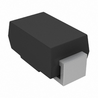
... US1A thru US1M Vishay General Semiconductor PACKAGE OUTLINE DIMENSIONS in inches (millimeters) DO-214AC (SMA) 0.065 (1.65) 0.049 (1.25) 0.177 (4.50) 0.157 (3.99) 0.090 (2.29) 0.078 (1.98) 0.060 (1.52) 0.030 (0.76) 0.194 (4.93) www.vishay.com For technical questions within your region, please contact one of the following: 4 PDD-Americas@vishay ...
Page 5
... Vishay product could result in personal injury or death. Customers using or selling Vishay products not expressly indicated for use in such applications their own risk and agree to fully indemnify and hold Vishay and its distributors harmless from and against any and all claims, liabilities, expenses and damages arising or resulting in connection with such use or sale, including attorneys fees, even if such claim alleges that Vishay or its distributor was negligent regarding the design or manufacture of the part ...