APT80GA90LD40 Microsemi Power Products Group, APT80GA90LD40 Datasheet
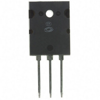
IGBT 900V 145A 625W TO-264

APT80GA90LD40

Manufacturer Part Number
APT80GA90LD40
Description
IGBT 900V 145A 625W TO-264
Manufacturer
Microsemi Power Products Group
Series
POWER MOS 8™r
Datasheet

Specifications of APT80GA90LD40

Igbt Type
PT
Voltage - Collector Emitter Breakdown (max)
900V
Vce(on) (max) @ Vge, Ic
3.1V @ 15V, 47A
Current - Collector (ic) (max)
145A
Power - Max
625W
Input Type
Standard
Mounting Type
Through Hole
Package / Case
TO-264
Lead Free Status / RoHS Status
Lead free / RoHS Compliant
Other names
Q4945437

Available stocks

Company
Part Number
Manufacturer
Quantity
Price
Part Number:
APT80GA90LD40
Manufacturer:
APT
Quantity:
2 000
Static Characteristics
Absolute Maximum Ratings
POWER MOS 8
through leading technology silicon design and lifetime control processes. A reduced E
V
gate charge and a greatly reduced ratio of C
delay times and simple gate drive. The intrinsic chip gate resistance and capacitance of the
poly-silicone gate structure help control di/dt during switching, resulting in low EMI, even
when switching at high frequency.
Symbol
Symbol
FEATURES
CE(ON)
T
V
SSOA
V
V
J
• Fast switching with low EMI
• Very Low E
• Ultra low C
• Low conduction loss
• Low gate charge
• Increased intrinsic gate resistance for low EMI
• RoHS compliant
V
V
BR(CES)
, T
I
I
I
P
I
I
T
CE(on)
GE(th)
GES
CM
CES
ces
C1
C2
GE
D
L
STG
tradeoff results in superior effi ciency compared to other IGBT technologies. Low
Parameter
Collector Emitter Voltage
Continuous Collector Current @ T
Pulsed Collector Current
Gate-Emitter Voltage
Total Power Dissipation @ T
Switching Safe Operating Area @ T
Operating and Storage Junction Temperature Range
Lead Temperature for Soldering: 0.063" from Case for 10 Seconds
Collector-Emitter Breakdown Voltage
Collector-Emitter On Voltage
Gate Emitter Threshold Voltage
Zero Gate Voltage Collector Current
Gate-Emitter Leakage Current
Parameter
res
off
®
is a high speed Punch-Through switch-mode IGBT. Low E
for maximum effi ciency
for improved noise immunity
High Speed PT IGBT
2
1
C
= 25°C
C
C
Microsemi Website - http://www.microsemi.com
= 25°C
= 100°C
J
res
= 150°C
/C
ies
T
provide excellent noise immunity, short
J
= 25°C unless otherwise specifi ed
V
V
CE
V
I
GE
C
V
GE
Test Conditions
V
= 47A
= 900V,
GE
= 15V,
GE
= 0V
= 0V, I
V
=V
TYPICAL APPLICATIONS
• ZVS phase shifted and other full bridge
• Half bridge
• High power PFC boost
• Welding
• UPS, solar, and other inverters
• High frequency, high effi ciency industrial
GS
CE
= ±30V
, I
C
C
= 1.0mA
= 1mA
T
T
T
T
off
J
J
J
J
= 25°C
= 125°C
= 25°C
= 125°C
is achieved
off
APT80GA90B2D40
-
Min
Combi (IGBT and Diode)
900
3
APT80GA90B2D40
APT80GA90LD40
239A @ 900V
APT80GA90LD40
-55 to 150
Ratings
Typ
900
145
239
625
300
±30
2.5
2.2
4.5
80
Max
1500
±100
350
3.1
6
900V
Unit
Unit
°C
μA
nA
W
V
V
V
A

Related parts for APT80GA90LD40

APT80GA90LD40 Summary of contents

Page 1

... 47A 1mA 900V ±30V GS Microsemi Website - http://www.microsemi.com APT80GA90B2D40 APT80GA90LD40 APT80GA90B2D40 is achieved off - off APT80GA90LD40 Combi (IGBT and Diode) Ratings 900 145 80 239 ±30 625 239A @ 900V -55 to 150 300 Min Typ Max 900 T = 25°C 2.5 3 125° 25°C ...

Page 2

Dynamic Characteristics Symbol Parameter C Input Capacitance ies C Output Capacitance oes C Reverse Transfer Capacitance res Q Total Gate Charge Gate-Emitter Charge ge Q Gate- Collector Charge gc SSOA Switching Safe Operating Area t Turn-On Delay ...

Page 3

ULTRAFAST SOFT RECOVERY RECTIFIER DIODE MAXIMUM RATINGS Symbol Characteristic / Test Conditions I Maximum Average Forward Current (T F(AV) I RMS Forward Current (Square wave, 50% duty) F(RMS) I Non-Repetitive Forward Surge Current (T FSM STATIC ELECTRICAL CHARACTERISTICS Symbol Characteristic ...

Page 4

Dynamic Characteristics 120 100 175° 125° 1.0 2 ANODE-TO-CATHODE VOLTAGE (V) F Figure 2. Forward Current vs. Forward Voltage 4000 T = 125° ...

Page 5

Dynamic Characteristics +18V Forward Conduction Current /dt - Rate of Diode Current Change Through Zero Crossing Maximum Reverse Recovery Current. RRM Reverse R ecovery Time, ...

Related keywords