IRGB10B60KDPBF International Rectifier, IRGB10B60KDPBF Datasheet
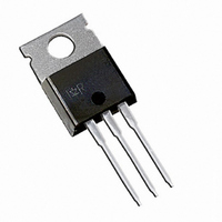
IGBT W/DIODE 600V 22A TO-220AB

IRGB10B60KDPBF

Manufacturer Part Number
IRGB10B60KDPBF
Description
IGBT W/DIODE 600V 22A TO-220AB
Manufacturer
International Rectifier
Type
Ultrafastr

Specifications of IRGB10B60KDPBF

Igbt Type
NPT
Voltage - Collector Emitter Breakdown (max)
600V
Vce(on) (max) @ Vge, Ic
2.2V @ 15V, 10A
Current - Collector (ic) (max)
22A
Power - Max
156W
Input Type
Standard
Mounting Type
Through Hole
Package / Case
TO-220-3 (Straight Leads)
Capacitance, Gate
620 pF
Current, Collector
22 A
Energy Rating
390 μJ
Package Type
TO-220AB
Polarity
N-Channel
Power Dissipation
156 W
Resistance, Thermal, Junction To Case
0.8 °C/W
Speed, Switching
10 to 30 kHz
Voltage, Collector To Emitter Shorted
600 V
Voltage, Collector To Emitter, Saturation
1.8 V
Transistor Type
IGBT
Dc Collector Current
22A
Collector Emitter Voltage Vces
2.2V
Power Dissipation Pd
104W
Collector Emitter Voltage V(br)ceo
600V
Operating Temperature Range
-55°C To +150°C
Rohs Compliant
Yes
Lead Free Status / RoHS Status
Lead free / RoHS Compliant
Other names
*IRGB10B60KDPBF

Available stocks

Company
Part Number
Manufacturer
Quantity
Price
Company:
Part Number:
IRGB10B60KDPBF
Quantity:
9 000
Features
Benefits
• Benchmark Efficiency for Motor Control.
• Rugged Transient Performance.
• Low EMI.
• Excellent Current Sharing in Parallel Operation.
INSULATED GATE BIPOLAR TRANSISTOR WITH
ULTRAFAST SOFT RECOVERY DIODE
• Low VCE (on) Non Punch Through IGBT Technology.
• Low Diode VF.
• 10µs Short Circuit Capability.
• Square RBSOA.
• Ultrasoft Diode Reverse Recovery Characteristics.
• Positive VCE (on) Temperature Coefficient.
• Lead-Free (only the TO-220AB version is currently
Thermal Resistance
Absolute Maximum Ratings
R
R
R
R
R
Wt
V
I
I
I
I
I
I
I
V
P
P
T
T
C
C
CM
LM
F
F
FM
available in a Lead-Free configuration)
J
STG
CES
GE
D
D
θJC
θJC
θCS
θJA
θJA
@ T
@ T
@ T
@ T
@ T
@ T
C
C
C
C
C
C
= 25°C
= 100°C
= 25°C
= 100°C
= 25°C
= 100°C
Junction-to-Case - IGBT
Junction-to-Case - Diode
Case-to-Sink, flat, greased surface
Junction-to-Ambient, typical socket mount
Junction-to-Ambient (PCB Mount, steady state)
Weight
Collector-to-Emitter Voltage
Continuous Collector Current
Pulsed Collector Current
Clamped Inductive Load Current
Diode Continuous Forward Current
Diode Maximum Forward Current
Gate-to-Emitter Voltage
Maximum Power Dissipation
Operating Junction and
Storage Temperature Range
Soldering Temperature, for 10 sec.
Parameter
Parameter
IRGB10B60KDPbF

G
TO-220AB
n-channel
300 (0.063 in. (1.6mm) from case)
Min.
–––
–––
–––
–––
–––
–––
E
C
-55 to +150
IRGS10B60KD
IRGB10B60KDPbF
Max.
± 20
600
156
Typ.
22
12
44
44
22
10
44
62
0.50
1.44
–––
–––
–––
–––
D
IRGSL10B60KD
2
V
I
t
V
Pak
C
sc
IRGS10B60KD
CES
CE(on)
= 12A, T
> 10µs, T
= 600V
typ. = 1.8V
Max.
IRGSL10B60KD
–––
–––
0.8
3.4
62
40
C
TO-262
=100°C
J
=150°C
Units
Units
°C/W
W
°C
V
A
V
g
1

Related parts for IRGB10B60KDPBF

IRGB10B60KDPBF Summary of contents

Page 1

... IRGB10B60KDPbF IRGS10B60KD IRGSL10B60KD 600V CES I = 12A > 10µ n-channel CE(on) 2 TO-220AB D Pak IRGB10B60KDPbF IRGS10B60KD Max. 600 ± 20 156 62 -55 to +150 300 (0.063 in. (1.6mm) from case) Min. Typ. ––– ––– ––– ––– ––– ...

Page 2

... IRGB10B60KDPBF/S/SL10B60KD Electrical Characteristics @ T Parameter V Collector-to-Emitter Breakdown Voltage (BR)CES Temperature Coeff. of Breakdown Voltage ∆V /∆T (BR)CES J V Collector-to-Emitter Saturation Voltage CE(on) V Gate Threshold Voltage GE(th Temperature Coeff. of Threshold Voltage ––– ∆ ∆ GE(th Forward Transconductance fe I Zero Gate Voltage Collector Current ...

Page 3

... IRGB10B60KDPBF/S/SL10B60KD Dimensions are shown in millimeters (inches) 10.54 (.415) 10.29 (.405) 2.87 (.113) 2.62 (.103) 15.24 (.600) 14.84 (.584 14.09 (.555) 13.47 (.530) 1.40 (.055) 3X 1.15 (.045) 2.54 (.100) 2X NOTES: 1 DIMENSIONING & TOLERANCING PER ANSI Y14.5M, 1982. 2 CONTROLLING DIMENSION : INCH E XAMPL HIS 1010 ...

Related keywords