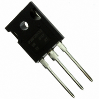
IRGP30B120KD-EP International Rectifier, IRGP30B120KD-EP Datasheet

IRGP30B120KD-EP
Specifications of IRGP30B120KD-EP
Available stocks
Related parts for IRGP30B120KD-EP
IRGP30B120KD-EP Summary of contents
Page 1
... R Case-to-Sink, flat, greased surface θCS R Junction-to-Ambient, typical socket mount θJA W Weight t Z Transient Thermal Impedance Junction-to-Case θJC www.irf.com IRGP30B120KD-EP G n-channel N-channel (Fig.1) (Fig.1) (Fig.3, Fig. CT.5) (Fig.4, Fig. CT.2) (Fig.2) (Fig.2) 300, (0.063 in. (1.6mm) from case) Min. ––– ––– ...
Page 2
... IRGP30B120KD-EP Electrical Characteristics @ TJ = 25°C (unless otherwise specified) Parameter V Collector-to-Emitter Breakdown Voltage (BR)CES ∆V / ∆Tj Temperature Coeff. of Breakdown Voltage (BR)CES Collector-to-Emitter Saturation V Voltage CE(on) V Gate Threshold Voltage GE(th) ∆V / ∆Tj Temperature Coeff. of Threshold Voltage GE(th) g Forward Transconductance fe I Zero Gate Voltage Collector Current ...
Page 3
... Tj < 150°C C 1000 100 100 V (V) CE www.irf.com 120 160 PULSED 2µs 10µ s 100µ s 1ms 10ms DC 1000 10000 IRGP30B120KD-EP Fig.2 - Power Dissipation vs. Case Temperature 320 280 240 200 160 120 120 T (°C) C Fig.4 - Reverse Bias SOA Tj = 150° 15V GE 1000 100 ...
Page 4
... IRGP30B120KD-EP Fig.5 - Typical IGBT Output Characteristics Tj= -40°C; tp=300µ 18V 15V 12V 10V Fig.7 - Typical IGBT Output Characteristics Tj=125°C; tp=300µ 18V 15V 12V 10V ( (V) Fig.6 - Typical IGBT Output Characteristics Tj=25°C; tp=300µ 18V 15V 12V 10V (V) CE Fig ...
Page 5
... V (V) GE www.irf.com =10A CE I =25A CE I =50A ( =10A CE I =25A CE I =50A IRGP30B120KD-EP Fig.10 - Typical Tj= 25° (V) GE Fig.12 - Typ. Transfer Characteristics V =20V; tp=20µs CE 250 Tj=25°C 225 Tj=125°C 200 175 150 125 100 75 50 Tj=125°C 25 Tj=25°C ...
Page 6
... IRGP30B120KD-EP Fig.13 - Typical Energy Loss vs Ic Tj=125°C; L=200µH; V Rg=22 Ω 8000 7000 6000 5000 4000 3000 2000 1000 (A) C Fig.15 - Typical Energy Loss vs Rg Tj=125°C; L=200µ =25A; V =15V CE GE 3500 3300 3100 2900 2700 2500 2300 2100 ...
Page 7
... I =25A; Tj=125° Rg=5 Ω Rg=51 Ω 500 (A/µs) F www.irf.com / =15V Rg=10 Ω Rg=22 Ω 1000 1500 IRGP30B120KD-EP Fig.18 - Typical Diode Tj=125°C; I =25A (ohms) Fig.20 - Typical Diode =600V; V =15V; Tj=125° 7000 5 Ω 10 Ω 22 Ω 6500 51 Ω 6000 5500 5000 ...
Page 8
... IRGP30B120KD-EP Fig.22 - Typical Capacitance =0V; f=1MHz GE 10000 1000 100 ( Fig.21 - Typ. Diode E rec Tj=125°C 2400 2200 2000 1800 1600 1400 1200 1000 800 ( ies C oes res 80 100 vs Ω 10 Ω 22 Ω 51 Ω Fig.23 - Typ. Gate Charge vs =25A; L=600µ 600V 120 Q , Total Gate Charge (nC) ...
Page 9
... Fig.24 - Normalized Transient Thermal Impedance, Junction-to-Case =0.5 0.2 0.1 0.1 0.05 0.02 0.01 0.01 SINGLE PULSE 0.001 0.00001 0.00010 www.irf.com Notes: 1. Duty factor Peak T 0.00100 0.01000 t , Rectangular Pulse Duration (sec) 1 IRGP30B120KD- thJC C 0.10000 1.00000 10.00000 9 ...
Page 10
... IRGP30B120KD- Driver DUT 10 L VCC DUT D 900V DUT diode clamp / DUT DUT / DRIVER VCC DUT 1000V VCC www.irf.com ...
Page 11
... I me (µS) www.irf.com 1.5 2.0 2 10% Peak - -20 -30 1.0 IRGP30B120KD-EP 900 800 700 TEST CURRENT 600 500 90% test current 400 t r 300 10% test current 200 100 0 Eon Loss -100 4.0 4.1 4.2 4 (µs) C 1200 1000 800 600 400 200 0 ...
Page 12
... IRGP30B120KD-EP EXAMPLE: THIS IS AN IRGP30B120KD-E WITH AS SEMBLY LOT CODE 5657 AS SEMBLED ON WW 35, 2000 IN THE ASS EMBLY LINE "H" Note: "P" embly line pos ition indicates "Lead-Free" IR WORLD HEADQUARTERS: 233 Kansas St., El Segundo, California 90245, USA Tel: (310) 252-7105 12 INTERNATIONAL RECTIF IER ...
Page 13
Note: For the most current drawings please refer to the IR website at: http://www.irf.com/package/ ...


