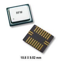
RX5001 RFM, RX5001 Datasheet - Page 4

RX5001
Manufacturer Part Number
RX5001
Description
RF Receiver 2G ASH Receiver 315 MHz 115.2kbps
Manufacturer
RFM
Type
Receiverr
Datasheet
1.RX5001.pdf
(10 pages)
Specifications of RX5001
Package / Case
SM-20L
Operating Frequency
315.2 MHz
Operating Supply Voltage
2.5 V, 3.3 V
Maximum Operating Temperature
+ 85 C
Minimum Operating Temperature
- 40 C
Mounting Style
SMD/SMT
Lead Free Status / RoHS Status
Lead free / RoHS Compliant
Available stocks
Company
Part Number
Manufacturer
Quantity
Price
Company:
Part Number:
RX5001
Manufacturer:
SYNERGY
Quantity:
5 000
www.RFM.com
©2008 by RF Monolithics, Inc.
ASH Receiver Theory of Operation
Introduction
RFM’s RX5000 series amplifier-sequenced hybrid (ASH) receivers
are specifically designed for short-range wireless control and data
communication applications. The receivers provide robust
operation, very small size, low power consumption and low
implementation cost. All critical RF functions are contained in the
hybrid, simplifying and speeding design-in. The ASH receiver can
be readily configured to support a wide range of data rates and
protocol requirements. The receiver features virtually no RF
emissions, making it easy to certify to short-range (unlicensed)
radio regulations.
Amplifier-Sequenced Receiver Operation
The ASH receiver’s unique feature set is made possible by its
system architecture. The heart of the receiver is the amplifier-
sequenced receiver section, which provides more than 100 dB of
stable RF and detector gain without any special shielding or
decoupling provisions. Stability is achieved by distributing the total
RF gain over time. This is in contrast to a superheterodyne
receiver, which achieves stability by distributing total RF gain over
multiple frequencies.
Figure 1 shows the basic block diagram and timing cycle for an
amplifier-sequenced receiver. Note that the bias to RF amplifiers
RFA1 and RFA2 are independently controlled by a pulse
generator, and that the two amplifiers are coupled by a surface
E-mail: info@rfm.com
Delay Line
Out
RFA1 Out
RF Input
Antenna
P1
P2
t
PW 1
t
PW2
ASH Receiver Block Diagram & Timing Cycle
SAW Filter
t
PRC
t
PRI
RFA1
P1
Figure 1
RF Data Pulse
Delay Line
Generator
Pulse
SAW
acoustic wave (SAW) delay line, which has a typical delay of
0.5 µs.
An incoming RF signal is first filtered by a narrow-band SAW filter,
and is then applied to RFA1. The pulse generator turns RFA1 ON
for 0.5 µs. The amplified signal from RFA1 emerges from the SAW
delay line at the input to RFA2. RFA1 is now switched OFF and
RFA2 is switched ON for 0.55 µs, amplifying the RF signal further.
The ON time for RFA2 is usually set at 1.1 times the ON time for
RFA1, as the filtering effect of the SAW delay line stretches the
signal pulse from RFA1 somewhat. As shown in the timing
diagram, RFA1 and RFA2 are never on at the same time, assuring
excellent receiver stability. Note that the narrow-band SAW filter
eliminates sampling sideband responses outside of the receiver
passband, and the SAW filter and delay line act together to provide
very high receiver ultimate rejection.
Amplifier-sequenced receiver operation has several interesting
characteristics that can be exploited in system design. The RF
amplifiers in an amplifier-sequenced receiver can be turned on and
off almost instantly, allowing for very quick power-down (sleep)
and wake-up times. Also, both RF amplifiers can be off between
ON sequences to trade-off receiver noise figure for lower average
current consumption. The effect on noise figure can be modeled as
if RFA1 is on continuously, with an attenuator placed in front of it
with a loss equivalent to 10*log
duty factor is the average amount of time RFA1 is ON (up to 50%).
Since an amplifier-sequenced receiver is inherently a sampling
RFA2
P2
Detector &
Low-Pass
Filter
10
(RFA1 duty factor), where the
Data
Out
RX5001 - 4/7/08
Page 4 of 10


