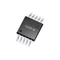
ATA5757-6DQJ Atmel, ATA5757-6DQJ Datasheet - Page 11

ATA5757-6DQJ
Manufacturer Part Number
ATA5757-6DQJ
Description
RF Transmitter ASK/FSK Transmitter 433MHz TPMS
Manufacturer
Atmel
Type
Transmitterr
Datasheet
1.ATAB5756.pdf
(20 pages)
Specifications of ATA5757-6DQJ
Package / Case
TSSOP-10
Operating Frequency
448 MHz
Mounting Style
SMD/SMT
Operating Supply Voltage
2.5 V, 3.3 V
Operating Temperature (min)
-40C
Operating Temperature (max)
125C
Operating Temperature Classification
Automotive
Operating Supply Voltage (typ)
2.5/3.3V
Operating Supply Voltage (max)
3.6V
Lead Free Status / RoHS Status
Lead free / RoHS Compliant
4.6
4702J–RKE–09/08
Application Circuits
For the supply voltage blocking capacitor C
4-7 on page 12
the power amplifier. For C
ance value and to enable it to realize Z
Together with the pins of ATA5756 and the PCB board wires, C
that suppresses the 1
the best suppression is achieved when C
ANT2.
The loop antenna should not exceed a width of 1.5 mm, otherwise the Q-factor of the loop
antenna is too high.
L
the load resonance frequency of the crystal. Normally, a value of 10 pF results in a 12 pF
load-capacitance crystal due to the board parasitic capacitances and the inductive impedance of
the XTO1 pin.
1
(50 nH to 100 nH) can be printed on the PCB. C
and
Figure 4-8 on page
st
harmonic, hence the position of C
2
, two capacitors in series should be used to achieve a better toler-
Load,opt
13). C
1
3
is placed as close as possible to the pins ANT1 and
, a value of 68 nF/X7R is recommended (see
by using capacitors with standard values.
1
and C
4
should be selected so that the XTO runs on
2
are used to match the loop antenna to
1
ATA5756/ATA5757
on the PCB is important. Normally,
1 forms
a series resonance loop
Figure
11


