EA1-B0-12-650-21A-BB Carling Technologies, EA1-B0-12-650-21A-BB Datasheet - Page 4
EA1-B0-12-650-21A-BB
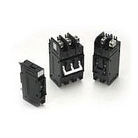
Manufacturer Part Number
EA1-B0-12-650-21A-BB
Description
Circuit Breakers 50A ONE POLE
Manufacturer
Carling Technologies
Datasheet
1.EA1-B0-14-810-32E-BC.pdf
(8 pages)
Specifications of EA1-B0-12-650-21A-BB
Product Type
Circuit Breakers
Current Rating
50 Amps
Voltage Rating
600 VoltsAC, 125 VoltsDC
Trip Time
0.15 s to 0.8 s
Mounting Style
Panel
Termination Style
Threaded Stud
Circuit Function
Series Trip (Current)
Product
Hydraulic Magnetic Circuit Breakers
Number Of Poles
1 Pole
Actuator Type
Handle
Lead Free Status / RoHS Status
Lead free / RoHS Compliant


www.carlingtech.com
NOTES
1
2
3
4
1
Series
E
A06
A12
A18
A24
A32
A48
7 CURRENT RATING (AMPERES)
020
025
030
035
040
045
050
055
060
065
070
075
080
085
090
090
210
215
220
225
230
OR VOLTAGE COIL (MIN. TRIP RATING, VOLTS)
1 SERIES
E
2 ACTUATOR
Handle
A
3 POLES
1
2
4 CIRCUIT
A
B
C
D
6 FREQUENCY & DELAY
03
10
12
14
16
20
22
24
26
30
32
5 AUXILIARY SWITCH
0
2
3
4
3
3
5
5
VDE approval on 1-5 poles only. Standard multi-pole units identical poles except when
specifying auxiliary switch - (see Note 4). For mixed ratings, consult factory.
Switch Only & Series Trip construction available w/either front or back connected terminals.
Shunt construction available w/back connected terminals, (Terminal Codes 1 & 2) only.
Circuit Codes B,C & D are VDE approved.
Switch Only construction: 30 amps or less select Current Rating Code 630; 31-70 amps,
select Current Rating code 670; 71-100 amps, select Current Rating Code 810; 101-125
amps Select Current Rating Code 912. Switch Only is VDE approved only if tied to a pro-
tected pole.
Auxiliary Switch available on Switch Only and Series Trip units. On multi-pole units, only
one auxiliary switch is normally supplied mounted in the extreme right pole. Back mounted
units require special mounting provisions when auxiliary switch is specified. VDE approval
on Auxilary Switch Codes 0,2,3 & 4 only.
12 DC, 10 DC
18 DC, 15 DC
24 DC, 20 DC
32 DC, 25 DC
48 DC, 40 DC
DC 50/60Hz, Switch Only
DC Instantaneous
DC Short
DC Medium
DC Long
50/60Hz Instantaneous
50/60Hz Short
50/60Hz Medium
50/60Hz Long
DC, 50/60Hz Instantaneous
DC, 50/60Hz Short
Handle, one per pole
Switch Only (No Coil)
Series Trip (Current)
Series Trip (Voltage)
Shunt Trip (Current)
without Auxiliary Switch
S.P.D.T. 0.110 Q.C. Terminals
S.P.D.T. 0.139 Solder Lug
S.P.D.T. 0.110 Q.C. Terminals
(Gold Contacts)
0.020
0.025
0.030
0.035
0.040
0.045
0.050
0.055
0.060
0.065
0.070
0.075
0.080
0.085
0.090
0.095
0.100
0.150
0.200
0.250
0.300
6 DC, 5 DC
2
Actuator
One
Two
A 2
1
2
3
Poles
235
240
245
250
255
260
265
270
275
280
285
290
295
410
512
415
517
420
522
425
527
4
A65
B25 125 DC, 100 DC
J06
J12
J18
J24
0.350
0.400
0.450
0.500
0.550
0.600
0.650
0.700
0.750
0.800
0.850
0.900
0.950
1.000
1.250
1.500
1.750
2.000
2.250
2.500
2.750
3
4
–
65 DC, 55 DC
12 AC, 10 AC
18 AC, 15 AC
24 AC, 20 AC
4
Circuit
7
Three
Four
B
6 AC, 5 AC
430
435
440
445
450
455
460
465
470
475
480
485
490
495
610
710
611
711
612
712
613
34
36
62
64
66
72
74
76
92
94
96
E
F
G
6
7
8
9
6
6
6
5
Auxiliary
Switch
10.000
10.500
12.000
12.500
13.000
11.000
11.500
Shunt Trip (Voltage)
Relay Trip (Current)
Relay Trip (Voltage)
S.P.D.T. 0.110 Q.C. Terminals
S.P.D.T. 0.110 Q.C. Terminals
(Gold Contacts)
S.P.D.T. 0.187 Q.C. Terminals
S.P.D.T. 0.187 Q.C. Terminals
DC, 50/60Hz Medium
DC, 50/60Hz Long
50/60Hz Short, Hi-Inrush
50/60Hz Medium, Hi-Inrush
50/60Hz Long, Hi-Inrush
DC, Short,Hi-Inrush
DC,Medium, Hi-Inrush
DC, Long, Hi-Inrush
DC, 50/60Hz Short, Hi-Inrush
DC, 50/60Hz Medium,
Hi-Inrush
DC, 50/60Hz Long, Hi-Inrush
0
3.000
3.500
4.000
4.500
5.000
5.500
6.000
6.500
7.000
7.500
8.000
8.500
9.000
9.500
5
J48
J65
K20 120 AC, 65 AC
L40 240 AC, 130 AC
5
6
–
614
615
616
617
618
620
622
624
625
630
635
640
650
660
670
680
690
810 100.000
811 110.000
812 120.000
912
48 AC, 40 AC
65 AC, 55 AC
6
Frequency
& Delay
24
Five
Six
8
125.000
14.000
15.000
16.000
17.000
18.000
20.000
22.000
24.000
25.000
30.000
35.000
40.000
50.000
60.000
70.000
80.000
90.000
–
E-Series Handle UL Recognized – Ordering Scheme
7
Current Rating
450
5
6
7
8
9
10
11
12
13
14
15
16
8 TERMINAL
BACK CONNECTED (FRONT MOUNTED ONLY)
1
2
A
B
FRONT CONNECTED (BACK MOUNTED ONLY)
3
C
4
D
5
E
6
F
7
G
8
H
9
J
9 ACTUATOR COLOR & LEGEND
Actuator Color
Color:
White
Black
Red
Green
Blue
Yellow
Gray
Orange
10 MOUNTING/BARRIERS
BACK CONNECTED (FRONT MOUNTED ONLY)
A
B
FRONT CONNECTED (BACK MOUNTED ONLY)
C
D
E
F
11 MAXIMUM APPLICATION RATING
12 AGENCY APPROVAL
B
D
A
B
C
D
E
F
9
9
10
10
10
11
11
9
9
11
16
Voltage Trip Coils are not rated for continuous duty. Available only with Frequency & Delay
Codes 10 & 20. Series Trip construction with a voltage coil s VDE approved only if tied to a
protected pole.
Frequency & Delay Codes 92,94 & 96 are not VDE Certified.
Current Coil Ratings 0.100 - 100 ams are VDE Certified.
125 A rating (Code 912) available as a Switch Only (Circuit Code A), rated 125 VDC (Code B).
An Anti-Flash Over Barrier is supplied between poles on multi-pole units with 10-32
(Terminal Code 1). 1/4-20 (Code 2), M5 (Code A), and M6 (Code B) terminals per UL
requirement.
Box Wire Connector will accept #14 through 0 AWG. copper wire or #12 through 0 AWG.
aluminum wire.
Box Wire Connector with Pressure Plate for stranded wire, consult factory for details.
Terminal Codes A,B,D,E,G & H are not VDE Certified.
VDE approvals require Dual (I-O, ON-OFF) or I-O markings on all handles.
Back Mounted breakers can also be front mounted by utilizing the proper front panel
mounting inserts normally supplied. However, terminal connections must be made prior to
mounting.
Application ratings B,D,J,T & W are available with VDE.
415, 480 & 600 VAC ratings require 3 or 4 pole break 3Ø and 2 pole break 1Ø.
10-32 Stud (All Terminals)
1/4-20 Stud (All Terminals)
M5 Stud (Line & Load)
M6 Stud (Line & Load)
Box Wire Connector (Line & Load)
Box Wire Connector w/ Pressure Plate (Line & Load)
10-32 Screw (Line & Load)
M5 Screw (Line & Load)
10-32 “Bus-Type” Screw (Line), 10-32 Screw (Load)
M5 “Bus-Type” Screw (Line), 10-32 Screw (Load)
10-32 “Bus-Type” Screw (Line), Box Wire Connector (Load)
10-32 “Bus-Type” Screw (Line), Box Wire Connector
w/ Pressure Plate (Load)
1/4-20 Screw (Line & Load)
M6 Screw (Line & Load)
1/4-20 “Bus-Type” Screw (Line), 1/4-20 Screw (Load)
M6 “Bus-Type” Screw (Line), M6 Screw (Load)
1/4-20 “Bus-Type” Screw (Line), Box Wire Connector (Load)
1/4-20 “Bus-Type” Screw (Line), Box Wire Connector
w/ Pressure Plate (Load)
Mounting Inserts
6-32
ISO M3
Back Mounting Foot Type
Short
Short
Long
Long
65 VDC, 120 A
125 VDC, 120 A
120/240 VAC, 100 A
240 VAC, 100 A
277/480 VAC, 100 A
277 VAC, 100 A
UL 1077 / UL508 Recognized & CSA Accepted
UL 1077 Recognized, CSA Accepted, & VDE Certified
–
12
8
Terminal
Marking:
I-O
A
C
F
H
K
M
P
R
1 2 A
ON-OFF
B
D
G
J
L
N
Q
S
9
Actuator
Color
13
Front Mounting Inserts (Optional Use)
6-32
ISO M3
6-32
ISO M3
15
10
Mounting/
Barriers
Dual
1
2
3
4
5
6
7
8
G
H
J
L
T
W
16
16
16
16
16
600 VAC, 100 A
480 VAC, 100 A
415 VAC, 100 A
160 VDC, 100 A
125 VDC/240 VAC, 100 A
125 VDC/415 VAC, 100 A
14
–
Marking Color:
Black
White
White
White
White
Black
Black
Black
11
Maximum
Application
Rating
C
MAX. RATING
MAX. RATING
12
Agency
Approval
100 A
100 A
100 A
100 A
100 A
100 A
100 A
100 A
100 A
100 A
100 A
100 A
B
50 A
50 A
50 A
50 A
50 A
50 A
105
Related parts for EA1-B0-12-650-21A-BB
Image
Part Number
Description
Manufacturer
Datasheet
Request
R

Part Number:
Description:
Toggle Switches CARLING TECHNOLOGIES
Manufacturer:
Carling Technologies
Datasheet:
Part Number:
Description:
CARLING POWER SWITCH LIGHTED 10 AMP 250 VOLT AC
Manufacturer:
Carling Technologies
Part Number:
Description:
CARLING SWITCH
Manufacturer:
Carling Technologies

Part Number:
Description:
SWITCH PB SPST OFF-MOM SCRW TERM
Manufacturer:
Carling Technologies
Datasheet:
Part Number:
Description:
SWITCH
Manufacturer:
Carling Technologies
Datasheet:

Part Number:
Description:
INDUCTOR PLATE FOR THERMAL BRKR
Manufacturer:
Carling Technologies

Part Number:
Description:
CIRCUIT BREAKER ROCKER 9A SP BK
Manufacturer:
Carling Technologies
Datasheet:

Part Number:
Description:
CIRCUIT BREAKER MAGNETIC 20A
Manufacturer:
Carling Technologies
Datasheet:
Part Number:
Description:
LIGHT INDICATOR GRN 12VDC PNLMNT
Manufacturer:
Carling Technologies
Part Number:
Description:
CONTURA ILL INDICATOR 12V RED
Manufacturer:
Carling Technologies
Part Number:
Description:
Current Regulator Diodes CURRENT REGULATOR DIODES 3.6mA
Manufacturer:
Carling Technologies
Part Number:
Description:
Rocker Switches
Manufacturer:
Carling Technologies
Datasheet: