MFU0603-FFP1 4A0 Vishay, MFU0603-FFP1 4A0 Datasheet - Page 11
MFU0603-FFP1 4A0
Manufacturer Part Number
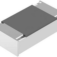
MFU0603-FFP1 4A0
Description
Fuses 4 AMP 32V
Manufacturer
Vishay
Type
Thin Film Chip Fusesr
Series
MFUr
Datasheet
1.MFU0805FF01000P500.pdf
(13 pages)
Specifications of MFU0603-FFP1 4A0
Current Rating
4 Amps
Voltage Rating
32 Volts
Fuse Size / Group
0603
Termination Style
SMD/SMT
Body Material
Metal Alloy, Ceramic
Dimensions
1.55 mm L x 0.85 mm W
Product
Surface Mount Fuse
Interrupt Rating
50 Amps at 32 VoltsDC
Mounting Style
SMD/SMT
Operating Temperature Range
+ 15 C to + 35 C
Fuse Type
Very Fast Acting
Lead Free Status / RoHS Status
Lead free / RoHS Compliant


TEST AND REQUIREMENTS
All tests are carried out in accordance with the following
specifications:
IEC 60127-1, Miniature fuse - Part 1: Definitions for miniature
fuses and general requirements for miniature fuse-links
IEC 60127-4, Universal Modular Fuse Links (UMF)
UL 248-1, Low voltage fuses - Part 1: General requirements
UL 248-14, Low voltage fuses - Part 14: Supplemental fuses
For the full test schedule refer to the documents listed above.
The testing also covers most of the requirements specified
by METI and CCC.
The tests are carried out in accordance with IEC 60068 and
under standard atmospheric conditions in accordance with
IEC 60068-1, 5.3. Climatic category LCT/UCT/56 (rated
temperature range: Lower category temperature, upper
category temperature; damp heat, long term, 56 days) is
valid.
Document Number: 28747
Revision: 06-May-10
CLAUSE
TEST PROCEDURES AND REQUIREMENTS
8.3.2
8.6.2
8.7.2
9.2.1
9.3.2
9.3.3
60127-4
IEC
METHOD
60068-2
21 (U
58 (Td)
58 (Td)
TEST
IEC
-
-
-
e1
)
characteristics
soldering heat
Resistance to
Time/current
Solderability
temperature
at nominal
resistance
Substrate
Breaking
Residual
bending
capacity
TEST
For technical questions, contact:
Cold resistance at 0.1 x I
destructive testing under
overcurrent conditions
(DC-Current)
Solder bath method; SnAg3Cu0.5 or SnAg3.5;
Thin Film Chip Fuses
Solder bath method; SnPb40;
(IR/forced gas convection);
(215 ± 3) °C; (3 ± 0.3) s
(245 ± 3) °C; (2 ± 0.2) s
(260 ± 5) °C; (10 ± 1) s
(260 ± 5) °C; (10 ± 1) s
50 A at rated voltage
50 A at rated voltage
Solder bath method;
non-activated flux;
non-activated flux;
acc. to UL 248-14
acc. to UL 248-14
Reflow method 2
PROCEDURE
Depth 1 mm;
rate 1 mm/s
R
;
1 times
thinfilm.chipfuse@vishay.com
MFU 0402
MFU 0402 0.8 A ≤ I
MFU 0603
MFU 0805
MFU 1206
Unless otherwise specified the following values apply:
Temperature: 15 °C to 35 °C
Relative humidity: 45 % to 75 %
Air pressure: 86 kPa to 106 kPa (860 mbar to 1060 mbar).
The components are mounted for testing on printed-circuit
boards in accordance with IEC 60127-4, unless otherwise
specified.
The requirements stated in the Test Procedures and
Requirements table are based on the required tests and
permitted limits of IEC 60127-1 and IEC 60127-4
respectively. However, some additional tests and a number
of improvements against those minimum requirements have
been included.
I
R
I
I
I
R
R
R
≤ 0.75 A
≤ 5.0 A
≤ 5.0 A
≤ 6.3 A
R
≤ 3.15 A
Optical inspection with naked eye
Good tinning (≥ 95 % covered);
Good tinning (≥ 95 % covered);
Vishay Beyschlag
at 10 x I
at 10 x I
PERMISSIBLE CHANGE
At 1.25 x I
At 1.25 x I
at 2.0 x I
at 2.0 x I
Insulation resistance
higher than 0.1 MΩ
No visible damage
No visible damage
No visible damage
REQUIREMENTS
no visible damage
no visible damage
no visible damage
at 2.0 x U
ΔR/R ≤ ± 10 %
ΔR/R ≤ ± 10 %
ΔR/R ≤ ± 10 %
MFU Series
R
R
, t
, t
R
R
, t
pre-arc
pre-arc
R
R
, t
, t
, t
pre-arc
pre-arc
pre-arc
pre-arc
R
www.vishay.com
(DC)
< 0.001 s
< 0.001 s
< 60 s
< 5 s
> 1 h
> 1 h
11
Related parts for MFU0603-FFP1 4A0
Image
Part Number
Description
Manufacturer
Datasheet
Request
R

Part Number:
Description:
357-036-542-201 CARDEDGE 36POS DL .156 BLK LOPRO
Manufacturer:
Vishay
Datasheet:
Part Number:
Description:
357-036-542-201 CARDEDGE 36POS DL .156 BLK LOPRO
Manufacturer:
Vishay
Datasheet:
Part Number:
Description:
357-036-542-201 CARDEDGE 36POS DL .156 BLK LOPRO
Manufacturer:
Vishay
Datasheet:
Part Number:
Description:
357-036-542-201 CARDEDGE 36POS DL .156 BLK LOPRO
Manufacturer:
Vishay
Datasheet:
Part Number:
Description:
357-036-542-201 CARDEDGE 36POS DL .156 BLK LOPRO
Manufacturer:
Vishay
Datasheet:
Part Number:
Description:
357-036-542-201 CARDEDGE 36POS DL .156 BLK LOPRO
Manufacturer:
Vishay
Datasheet:
Part Number:
Description:
357-036-542-201 CARDEDGE 36POS DL .156 BLK LOPRO
Manufacturer:
Vishay
Datasheet:
Part Number:
Description:
357-036-542-201 CARDEDGE 36POS DL .156 BLK LOPRO
Manufacturer:
Vishay
Datasheet:
Part Number:
Description:
357-036-542-201 CARDEDGE 36POS DL .156 BLK LOPRO
Manufacturer:
Vishay
Datasheet:
Part Number:
Description:
357-036-542-201 CARDEDGE 36POS DL .156 BLK LOPRO
Manufacturer:
Vishay
Datasheet:
Part Number:
Description:
357-036-542-201 CARDEDGE 36POS DL .156 BLK LOPRO
Manufacturer:
Vishay
Datasheet:
Part Number:
Description:
357-036-542-201 CARDEDGE 36POS DL .156 BLK LOPRO
Manufacturer:
Vishay
Datasheet:
Part Number:
Description:
357-036-542-201 CARDEDGE 36POS DL .156 BLK LOPRO
Manufacturer:
Vishay
Datasheet:
Part Number:
Description:
357-036-542-201 CARDEDGE 36POS DL .156 BLK LOPRO
Manufacturer:
Vishay
Datasheet:
Part Number:
Description:
357-036-542-201 CARDEDGE 36POS DL .156 BLK LOPRO
Manufacturer:
Vishay
Datasheet: