MFU0603-FFP1 4A0 Vishay, MFU0603-FFP1 4A0 Datasheet - Page 3
MFU0603-FFP1 4A0
Manufacturer Part Number
MFU0603-FFP1 4A0
Description
Fuses 4 AMP 32V
Manufacturer
Vishay
Type
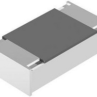
Thin Film Chip Fusesr
Series
MFUr
Datasheet
1.MFU0805FF01000P500.pdf
(13 pages)
Specifications of MFU0603-FFP1 4A0
Current Rating
4 Amps
Voltage Rating
32 Volts
Fuse Size / Group
0603
Termination Style
SMD/SMT
Body Material
Metal Alloy, Ceramic
Dimensions
1.55 mm L x 0.85 mm W
Product
Surface Mount Fuse
Interrupt Rating
50 Amps at 32 VoltsDC
Mounting Style
SMD/SMT
Operating Temperature Range
+ 15 C to + 35 C
Fuse Type
Very Fast Acting
Lead Free Status / RoHS Status
Lead free / RoHS Compliant


DIMENSIONS
SOLDER PAD DIMENSIONS
Note
• The given solder pad dimensions reflect the considerations for board design and assembly as outlined e.g. in standards IEC 61188-5-x, or in
Document Number: 28747
Revision: 06-May-10
DIMENSIONS - Chip fuse types, mass and relevant physical dimensions
TYPE
MFU 0402
MFU 0603 0.45 + 0.1/- 0.05
MFU 0805 0.45 + 0.1/- 0.05
MFU 1206
RECOMMENDED SOLDER PAD DIMENSIONS
TYPE
MFU 0402
MFU 0603
MFU 0805
MFU 1206
publication IPC-7351. They do not guarantee any supposed thermal properties, particularly as these are also strongly influenced by many other
parameters.
0.32 ± 0.07
0.55 ± 0.1
(mm)
H
(mm)
0.55
0.80
1.40
G
-
3.2 + 0.1/- 0.2
1.55 ± 0.05
For technical questions, contact:
1.0 ± 0.05
2.0 ± 0.1
(mm)
(mm)
WAVE SOLDERING
1.10
1.25
1.50
L
Y
-
H
W W
T
1.25 ± 0.15
(mm)
0.5 ± 0.05
0.85 ± 0.1
1.6 ± 0.15
1.10
1.50
1.90
T
Thin Film Chip Fuses
X
2
-
(mm)
W
T
1
Z
(mm)
2.75
3.30
4.40
L
Z
> 75 % of W
> 75 % of W
> 75 % of W
> 75 % of W
-
thinfilm.chipfuse@vishay.com
G
(mm)
W
T
Y
(mm)
0.35
0.65
0.90
1.50
G
0.2 + 0.1/- 0.15
0.3 + 0.15/- 0.2
0.4 + 0.1/- 0.2
0.5 ± 0.25
(mm)
T
1
REFLOW SOLDERING
X
(mm)
0.55
0.70
0.90
1.15
Y
0.3 + 0.15/- 0.2
0.4 + 0.1/- 0.2
0.5 ± 0.25
0.2 ± 0.1
Vishay Beyschlag
(mm)
T
2
(mm)
0.55
0.95
1.40
1.75
MFU Series
X
www.vishay.com
MASS
(mg)
0.65
1.9
4.7
9.5
(mm)
1.45
2.05
2.70
3.80
Z
3
Related parts for MFU0603-FFP1 4A0
Image
Part Number
Description
Manufacturer
Datasheet
Request
R

Part Number:
Description:
357-036-542-201 CARDEDGE 36POS DL .156 BLK LOPRO
Manufacturer:
Vishay
Datasheet:
Part Number:
Description:
357-036-542-201 CARDEDGE 36POS DL .156 BLK LOPRO
Manufacturer:
Vishay
Datasheet:
Part Number:
Description:
357-036-542-201 CARDEDGE 36POS DL .156 BLK LOPRO
Manufacturer:
Vishay
Datasheet:
Part Number:
Description:
357-036-542-201 CARDEDGE 36POS DL .156 BLK LOPRO
Manufacturer:
Vishay
Datasheet:
Part Number:
Description:
357-036-542-201 CARDEDGE 36POS DL .156 BLK LOPRO
Manufacturer:
Vishay
Datasheet:
Part Number:
Description:
357-036-542-201 CARDEDGE 36POS DL .156 BLK LOPRO
Manufacturer:
Vishay
Datasheet:
Part Number:
Description:
357-036-542-201 CARDEDGE 36POS DL .156 BLK LOPRO
Manufacturer:
Vishay
Datasheet:
Part Number:
Description:
357-036-542-201 CARDEDGE 36POS DL .156 BLK LOPRO
Manufacturer:
Vishay
Datasheet:
Part Number:
Description:
357-036-542-201 CARDEDGE 36POS DL .156 BLK LOPRO
Manufacturer:
Vishay
Datasheet:
Part Number:
Description:
357-036-542-201 CARDEDGE 36POS DL .156 BLK LOPRO
Manufacturer:
Vishay
Datasheet:
Part Number:
Description:
357-036-542-201 CARDEDGE 36POS DL .156 BLK LOPRO
Manufacturer:
Vishay
Datasheet:
Part Number:
Description:
357-036-542-201 CARDEDGE 36POS DL .156 BLK LOPRO
Manufacturer:
Vishay
Datasheet:
Part Number:
Description:
357-036-542-201 CARDEDGE 36POS DL .156 BLK LOPRO
Manufacturer:
Vishay
Datasheet:
Part Number:
Description:
357-036-542-201 CARDEDGE 36POS DL .156 BLK LOPRO
Manufacturer:
Vishay
Datasheet:
Part Number:
Description:
357-036-542-201 CARDEDGE 36POS DL .156 BLK LOPRO
Manufacturer:
Vishay
Datasheet: