8-1393792-5 TE Connectivity, 8-1393792-5 Datasheet - Page 465
8-1393792-5
Manufacturer Part Number
8-1393792-5
Description
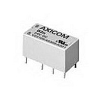
Electromechanical Relay DPDT 3A 5VDC 168Ohm Through Hole
Manufacturer
TE Connectivity
Type
Signal Relayr
Specifications of 8-1393792-5
Contact Arrangement
DPDT
Dc Coil Voltage
5 V
Coil Current
29.76 mA
Mounting
Through Hole
Relay Construction
Non-Latching
Coil Voltage Dc
5V
Contact Form
2 Form C
Voltage Rating (vdc)
220V
Voltage Rating (vac)
250V
Dropout Volt (min)
0.25VDCV
Coil Resistance
168Ohm
Pick-up Voltage (max)
4VDC
Maximum Power Rating
60W/125VA
Operate Time
5ms
Contact Current Rating
3A
Contact Material
AgNi/Au
Coil Suppression Diode
No
Push To Test Button
No
Led Indicator
No
Seal
Unsealed
Product Height (mm)
11mm
Product Depth (mm)
10mm
Product Length (mm)
20.2mm
Operating Temp Range
-25C to 85C
Pin Count
8
Mounting Style
Through Hole
Termination Style
PC Pin
Package / Case
DIP
Lead Free Status / Rohs Status
Compliant


Dimensions are shown for
reference purposes only.
WD25 Specifications
Nominal Operating Range: 120, 208, 277 or 480 VAC, selectable.
Maximum Sensing Range: 575VAC.
Nominal Frequency Range: 40-400.
Contact Form:
Sense Voltage:
Control Voltage:
Ordering Information
Our authorized distributor is more likely to stock these items.
WD25-001
WD25-013
WD25 Typical Hookup
NOTE:
For single dead bus option, connect the
generator to 1 & 2 and the bus to 4 & 5.
WD25 Operation
WD25 paralleling relays are used to ensure that two circuits are synchro-
nized. When voltage, phase relationship and frequency are within the se-
lected synchronizing limits, the output relay will energize. The WD25 paral-
leling relay allows for a generator to be brought online without damage or
system disturbance. WD25 series with a "dead bus" feature will energize
for a synchronized condition or an "on line" generator, "dead bus" condition.
This "dead bus" feature allows the generator to energize a dead bus. The
"double dead bus" feature permits paralleling of two buses when: (a) both
the line voltages are equal and in phase, or (b) when either bus is "hot" and
the other bus is "dead."
Voltage (nominal)
Synch Voltage (% of nom.)
Dead Bus Voltage (% of nom.)
Model WD25
Input Voltage (VDC)
Input Voltage (VAC)
Typical Part Number
1. Basic Series:
2. Type:
3. Dead Bus:
4. Control Voltage:
WD = DIN mount Protective Relay.
25 = Paralleling Relay.
00 = Double Dead Bus
01 = Single Dead Bus
02 = Generator to Generator
1 = 18 to 54VDC
2 = 13.5 to 32 VDC
3 = 100-200VDC or 100-140VAC.
2 form C (DPDT).
B
18 to 54
120
6 - 30% ( 4 - 20 electrical degree)
-0X1
–
Dimensions are in inches over
(millimeters) unless otherwise
specified.
10 - 70% (Dead Bus)
208
WD 25 -00
13.5 to 32
-0X2
–
277
100 to 200
100 to 140
-0X3
480
2
Catalog 1308242
Issued 3-03
WD25 Calibration
The calibration marks on the faceplate are provided only as guides. Proper
calibration requires using an accurate voltmeter. Use the following proce-
dure to calibrate the WD25:
1. Remove the cover.
2. Adjust the SYNC VOLTAGE control fully counterclockwise (CCW). Apply
3. Apply the maximum desired synchronization voltage to the LINE A (gen-
4. Slowly adjust the SYNC VOLTAGE control clockwise (CW) until the relay
WD25 Controls
WD25 Connections
WD25 Paralleling Relays
• Function 25
• ANSI/IEEE C37.90-1978
nominal voltage to the LINE B (bus) sensing terminals.
erator) terminals. This voltage should be in phase with LINE B (bus) volt-
age and have the same frequency.
energizes.
Specifications and availability
subject to change.
www.tycoelectronics.com
Technical support:
Refer to inside back cover.
KILOVAC
1309
Related parts for 8-1393792-5
Image
Part Number
Description
Manufacturer
Datasheet
Request
R

Part Number:
Description:
FFC / FPC Connectors 4 13 CONDUCTOR .100 Polyester
Manufacturer:
Tyco Electronics

Part Number:
Description:
#8 PRE-INSUL SEALED SPLICE
Manufacturer:
TE Connectivity
Datasheet:

Part Number:
Description:
TERMINAL,SOLIS R 8 8
Manufacturer:
TE Connectivity
Datasheet:

Part Number:
Description:
TERMINAL, RING TONGUE 3/8IN CRIMP YELLOW
Manufacturer:
TE Connectivity
Datasheet:

Part Number:
Description:
TERMINAL, RING TONGUE, #8, CRIMP, YELLOW
Manufacturer:
TE Connectivity
Datasheet:
Part Number:
Description:
TERMINAL, RING TONGUE, 3/8IN, CRIMP
Manufacturer:
TE Connectivity
Datasheet:
Part Number:
Description:
TERMINAL, RING TONGUE, #8, CRIMP, YELLOW
Manufacturer:
TE Connectivity
Datasheet:

Part Number:
Description:
TERMINAL,R PG 8 1/4
Manufacturer:
TE Connectivity
Datasheet:

Part Number:
Description:
TERMINAL, SPADE/FORK, #8, CRIMP, YELLOW
Manufacturer:
TE Connectivity
Datasheet:
Part Number:
Description:
TERMINAL, RING TONGUE, #8, CRIMP, YELLOW
Manufacturer:
TE Connectivity
Datasheet:

Part Number:
Description:
Manufacturer:
TE Connectivity
Datasheet:


Part Number:
Description:
Manufacturer:
TE Connectivity
Datasheet:

Part Number:
Description:
SOCKET, D, R/A, 9WAY, 4-40UNC
Manufacturer:
TE Connectivity
Datasheet:
Part Number:
Description:
Electromechanical Relay SPDT 15A 12VDC 400Ohm Through Hole
Manufacturer:
TE Connectivity
Datasheet: