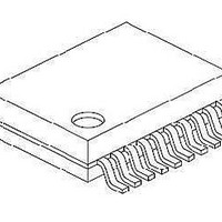
PIC16F1507-E/SS Microchip Technology, PIC16F1507-E/SS Datasheet - Page 9

PIC16F1507-E/SS
Manufacturer Part Number
PIC16F1507-E/SS
Description
3.5KB Flash, 128B RAM, 18 I/O, CLC, CWG, DDS, 10-bit ADC 20 SSOP .209in TUBE
Manufacturer
Microchip Technology
Series
PIC® 16Fr
Datasheets
1.PIC16F1507-EML.pdf
(266 pages)
2.PIC16F1507-EML.pdf
(26 pages)
3.PIC16F1507-EML.pdf
(40 pages)
Specifications of PIC16F1507-E/SS
Processor Series
PIC16
Core
PIC16F
Data Bus Width
8 bit
Program Memory Type
Flash
Program Memory Size
3.5 KB
Data Ram Size
128 B
Interface Type
ICSP
Maximum Clock Frequency
20 MHz
Number Of Programmable I/os
18
Number Of Timers
3
Operating Supply Voltage
2.3 V to 5.5 V
Maximum Operating Temperature
+ 125 C
Mounting Style
SMD/SMT
Package / Case
SSOP-20
Minimum Operating Temperature
- 40 C
Operating Temperature Range
- 40 C to + 125 C
Supply Current (max)
30 uA
Core Processor
PIC
Core Size
8-Bit
Speed
20MHz
Connectivity
-
Peripherals
Brown-out Detect/Reset, POR, PWM, WDT
Number Of I /o
17
Eeprom Size
-
Ram Size
128 x 8
Voltage - Supply (vcc/vdd)
2.3 V ~ 5.5 V
Data Converters
A/D 12x10b
Oscillator Type
Internal
Operating Temperature
-40°C ~ 125°C
Lead Free Status / Rohs Status
Details
1.1
1.2
1.3
2011 Microchip Technology Inc.
INTRODUCTION
HIGHLIGHTS
CLC CONFIGURATION TOOL PURPOSE
Chapter 1. CLC Configuration Tool Overview
The intention of this User’s Guide is to assist the reader in becoming acquainted with
the Configurable Logic Cell (CLC) Configuration Tool. It will explain how to setup the
tool and configure it with an applicable example of creating a Manchester encoder. This
document will help the reader become familiar with the purpose and functionality of the
CLC module and be able to use the CLC Configuration Tool with ease.
This chapter discusses:
• CLC Configuration Tool Purpose
• Installing the Program
• Configurable Designer Options
• Saving/Loading
The CLC consists of multiple combination and sequential circuits that can have their
functionality pre-programmed or programmed dynamically. This provides greater flexi-
bility and potential in embedded designs, since the CLC module can operate outside
the limitations of software execution and supports a vast amount of output designs.
The configuration tool's purpose is to streamline the setup process of the CLC module
by simulating the functionality of the registers in a graphical user interface (GUI). The
end result of using the tool will be a generated resource file, written in either C or
assembly, which can be dropped into an existing project to be included in a program.
The created file is custom generated, depending on the user inputs and preferences,
such as programming language.
CLC CONFIGURATION TOOL
USER’S GUIDE
DS41597A-page 9


