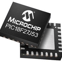
PIC16LF1906T-I/SO Microchip Technology, PIC16LF1906T-I/SO Datasheet - Page 177

PIC16LF1906T-I/SO
Manufacturer Part Number
PIC16LF1906T-I/SO
Description
14KB Flash, 512B RAM, LCD, 11x10b ADC, EUSART, NanoWatt XLP 28 SOIC .300in T/R
Manufacturer
Microchip Technology
Series
PIC® XLP™ 16Fr
Datasheet
1.PIC16LF1904-EMV.pdf
(288 pages)
Specifications of PIC16LF1906T-I/SO
Processor Series
PIC16LF
Core
PIC
Data Bus Width
8 bit
Program Memory Type
Flash
Data Ram Size
512 B
Maximum Clock Frequency
20 MHz
Number Of Programmable I/os
25
Number Of Timers
1 x 16-bit, 1 x 8-bit
Operating Supply Voltage
1.8 V to 5.5 V
Mounting Style
SMD/SMT
Package / Case
QFN-28
Core Processor
PIC
Core Size
8-Bit
Speed
20MHz
Connectivity
LIN, UART/USART
Peripherals
Brown-out Detect/Reset, LCD, POR, PWM, WDT
Number Of I /o
25
Program Memory Size
14KB (8K x 14)
Eeprom Size
-
Ram Size
512 x 8
Voltage - Supply (vcc/vdd)
1.8 V ~ 3.6 V
Data Converters
A/D 11x10b
Oscillator Type
Internal
Operating Temperature
-40°C ~ 85°C
Lead Free Status / Rohs Status
Details
- Current page: 177 of 288
- Download datasheet (3Mb)
18.4.1.5
1.
2.
3.
FIGURE 18-10:
FIGURE 18-11:
2011 Microchip Technology Inc.
TX/CK pin
(SCKP = 1)
TX/CK pin
(SCKP = 0)
TRMT bit
RX/DT
pin
Write to
TXREG Reg
TXIF bit
(Interrupt Flag)
TXEN bit
Note:
Initialize the SPBRGH, SPBRGL register pair
and the BRGH and BRG16 bits to achieve the
desired baud rate (see
Baud Rate Generator
Set the RX/DT and TX/CK TRIS controls to ‘1’.
Enable the synchronous master serial port by
setting bits SYNC, SPEN and CSRC. Set the
TRIS bits corresponding to the RX/DT and
TX/CK I/O pins.
‘1’
Synchronous Master Transmission
Set-up:
Sync Master mode, SPBRGL = 0, continuous transmission of two 8-bit words.
Write Word 1
TXREG reg
RX/DT pin
TX/CK pin
TRMT bit
TXEN bit
TXIF bit
Write to
SYNCHRONOUS TRANSMISSION
SYNCHRONOUS TRANSMISSION (THROUGH TXEN)
bit 0
Section 18.3 “EUSART
(BRG)”).
Write Word 2
bit 1
Word 1
bit 2
bit 0
Preliminary
bit 1
4.
5.
6.
7.
8.
9.
bit 7
Disable Receive mode by clearing bits SREN
and CREN.
Enable Transmit mode by setting the TXEN bit.
If 9-bit transmission is desired, set the TX9 bit.
If interrupts are desired, set the TXIE, GIE and
PEIE interrupt enable bits.
If 9-bit transmission is selected, the ninth bit
should be loaded in the TX9D bit.
Start transmission by loading data to the TXREG
register.
bit 2
bit 0
PIC16LF1904/6/7
Word 2
bit 1
bit 6
DS41569A-page 177
bit 7
bit 7
‘1’
Related parts for PIC16LF1906T-I/SO
Image
Part Number
Description
Manufacturer
Datasheet
Request
R

Part Number:
Description:
IC, 8BIT MCU, PIC16LF, 32MHZ, QFN-28
Manufacturer:
Microchip Technology
Datasheet:

Part Number:
Description:
IC, 8BIT MCU, PIC16LF, 32MHZ, QFN-28
Manufacturer:
Microchip Technology
Datasheet:

Part Number:
Description:
IC, 8BIT MCU, PIC16LF, 32MHZ, DIP-18
Manufacturer:
Microchip Technology
Datasheet:

Part Number:
Description:
IC, 8BIT MCU, PIC16LF, 20MHZ, TQFP-44
Manufacturer:
Microchip Technology
Datasheet:

Part Number:
Description:
7 KB Flash, 384 Bytes RAM, 32 MHz Int. Osc, 16 I/0, Enhanced Mid Range Core, Nan
Manufacturer:
Microchip Technology

Part Number:
Description:
14KB Flash, 512B RAM, LCD, 11x10b ADC, EUSART, NanoWatt XLP 28 SSOP .209in T/R
Manufacturer:
Microchip Technology
Datasheet:

Part Number:
Description:
MCU PIC 14KB FLASH XLP 28-SSOP
Manufacturer:
Microchip Technology

Part Number:
Description:
MCU PIC 14KB FLASH XLP 28-SOIC
Manufacturer:
Microchip Technology

Part Number:
Description:
MCU PIC 512B FLASH XLP 28-UQFN
Manufacturer:
Microchip Technology

Part Number:
Description:
MCU PIC 14KB FLASH XLP 28-SPDIP
Manufacturer:
Microchip Technology

Part Number:
Description:
MCU 7KB FLASH 256B RAM 40-UQFN
Manufacturer:
Microchip Technology

Part Number:
Description:
MCU 7KB FLASH 256B RAM 44-TQFP
Manufacturer:
Microchip Technology

Part Number:
Description:
MCU 14KB FLASH 1KB RAM 28-UQFN
Manufacturer:
Microchip Technology

Part Number:
Description:
MCU PIC 14KB FLASH XLP 40-UQFN
Manufacturer:
Microchip Technology

Part Number:
Description:
MCU PIC 14KB FLASH XLP 44-TQFP
Manufacturer:
Microchip Technology


