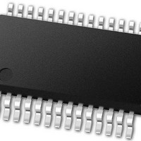
PIC24FJ64GA102-E/SS Microchip Technology, PIC24FJ64GA102-E/SS Datasheet - Page 267

PIC24FJ64GA102-E/SS
Manufacturer Part Number
PIC24FJ64GA102-E/SS
Description
16-bit, 16 MIPS, 64KB Flash, 8KB RAM, Nanowatt XLP 28 SSOP .209in TUBE
Manufacturer
Microchip Technology
Series
PIC® XLP™ 24Fr
Datasheet
1.PIC24FJ32GA102-ISP.pdf
(308 pages)
Specifications of PIC24FJ64GA102-E/SS
Processor Series
PIC24
Core
PIC24F
Data Bus Width
16 bit
Program Memory Type
Flash
Program Memory Size
64 KB
Data Ram Size
8192 B
Interface Type
I2C, SPI, UART
Maximum Clock Frequency
32 MHz
Number Of Programmable I/os
21
Number Of Timers
5
Operating Supply Voltage
2 V to 3.6 V
Maximum Operating Temperature
+ 125 C
Mounting Style
SMD/SMT
Package / Case
SSOP-28
Development Tools By Supplier
MPLAB Integrated Development Environment
Minimum Operating Temperature
- 40 C
Operating Temperature Range
- 40 C to + 125 C
Supply Current (max)
300 mA
Core Processor
PIC
Core Size
16-Bit
Speed
32MHz
Connectivity
I²C, IrDA, SPI, UART/USART
Peripherals
Brown-out Detect/Reset, LVD, POR, PWM, WDT
Number Of I /o
21
Eeprom Size
-
Ram Size
8K x 8
Voltage - Supply (vcc/vdd)
2 V ~ 3.6 V
Data Converters
A/D 10x10b
Oscillator Type
Internal
Operating Temperature
-40°C ~ 125°C
Lead Free Status / Rohs Status
Details
- Current page: 267 of 308
- Download datasheet (3Mb)
TABLE 28-4:
2010 Microchip Technology Inc.
DC CHARACTERISTICS
Operating Current (I
DC21
DC21a
DC21b
DC21f
DC21c
DC21d
DC21e
DC21g
DC20
DC20a
DC20b
DC20c
DC20d
DC20e
DC20f
DC20g
DC23
DC23a
DC23b
DC23c
DC23d
DC23e
DC23f
DC23g
Note 1:
Parameter
No.
2:
3:
4:
Data in “Typical” column is at 3.3V, 25°C unless otherwise stated. Parameters are for design guidance
only and are not tested.
The supply current is mainly a function of the operating voltage and frequency. Other factors, such as I/O pin
loading and switching rate, oscillator type, internal code execution pattern and temperature, also have an
impact on the current consumption. The test conditions for all I
with external square wave from rail to rail. All I/O pins are configured as inputs and pulled to V
MCLR = V
operational. No peripheral modules are operating and all of the Peripheral Module Disable (PMD) bits are set.
On-chip voltage regulator is disabled (DISVREG is tied to V
On-chip voltage regulator is enabled (DISVREG is tied to V
Detect (BOD) are enabled.
Typical
DC CHARACTERISTICS: OPERATING CURRENT (I
0.24
0.25
0.25
0.44
0.41
0.41
0.75
0.75
0.75
0.3
0.6
0.5
0.5
0.5
0.6
1.0
2.0
2.0
2.0
2.4
2.9
2.9
2.9
3.5
DD
DD
; WDT and FSCM are disabled. CPU, SRAM, program memory and data memory are
)
(1)
(2)
0.395
0.395
0.395
0.395
Max
0.78
0.78
0.78
0.78
0.75
0.75
0.75
0.75
1.4
1.4
1.4
1.4
3.0
3.0
3.0
3.0
4.2
4.2
4.2
4.2
Standard Operating Conditions: 2.0V to 3.6V (unless otherwise stated)
Operating temperature
Units
mA
mA
mA
mA
mA
mA
mA
mA
mA
mA
mA
mA
mA
mA
mA
mA
mA
mA
mA
mA
mA
mA
mA
mA
PIC24FJ64GA104 FAMILY
+125°C
+125°C
+125°C
+125°C
+125°C
+125°C
+25°C
+85°C
+25°C
+85°C
+25°C
+85°C
+25°C
+85°C
+25°C
+85°C
+25°C
+85°C
-40°C
-40°C
-40°C
-40°C
-40°C
-40°C
-40°C T
-40°C T
SS
DD
DD
). Low-Voltage Detect (LVD) and Brown-out
).
measurements are as follows: OSCI driven
A
A
DD
+85°C for Industrial
+125°C for Extended
Conditions
)
2.0V
3.3V
2.0V
3.3V
2.0V
3.3V
(3)
(4)
(3)
(4)
(3)
(4)
DS39951C-page 267
DD
0.5 MIPS
1 MIPS
4 MIPS
.
Related parts for PIC24FJ64GA102-E/SS
Image
Part Number
Description
Manufacturer
Datasheet
Request
R

Part Number:
Description:
Manufacturer:
Microchip Technology Inc.
Datasheet:

Part Number:
Description:
Manufacturer:
Microchip Technology Inc.
Datasheet:

Part Number:
Description:
Manufacturer:
Microchip Technology Inc.
Datasheet:

Part Number:
Description:
Manufacturer:
Microchip Technology Inc.
Datasheet:

Part Number:
Description:
Manufacturer:
Microchip Technology Inc.
Datasheet:

Part Number:
Description:
Manufacturer:
Microchip Technology Inc.
Datasheet:

Part Number:
Description:
Manufacturer:
Microchip Technology Inc.
Datasheet:

Part Number:
Description:
Manufacturer:
Microchip Technology Inc.
Datasheet:


