88 865 105 Crouzet USA, 88 865 105 Datasheet - Page 7
88 865 105
Manufacturer Part Number
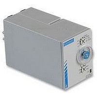
88 865 105
Description
TIMER, MULTIFUNCTION
Manufacturer
Crouzet USA
Datasheet
1.88_865_385.pdf
(12 pages)
Specifications of 88 865 105
Contact Configuration
SPCO
Nom Input Voltage
240VAC
Delay Time Range
0.1s To 100h
Relay Mounting
DIN Rail
Svhc
No SVHC (18-Jun-2010)
Adjustment Type
Screwdriver Slot
Coil Voltage Vdc Nom
24V
Contact
RoHS Compliant
Contact Current Ac Max
8A
Rohs Compliant
Yes


Timing range:
Digits:
Mounting:
Operating temperature:
Supply tolerance:
Weight:
Electrical life of relay:
Mechanical life of relay:
Rated power of relay:
Input signal:
Repetition accuracy:
Display accuracy:
Minimum pulse time:
(for start and reset)
Maximum reset time after
power down:
Input signal:
Power consumption(max):
Type
TOP948 12/24D
TOP948 24/48A
TOP948 110/240A
AZ511
4821
PRE48
TOP 948
Panel cut-out :
45 square
u
Start
3
4
2
5
1
6
+
1 1
+ 0.6
7
1 0
RST
8
9
+
0
GENERAL SPECIFICATIONS
+
CONNECTION
DIMENSIONS
5,5
69,2
Panel thickness 1 to 3.5 mm
Function
Multifunction
Multifunction
Multifunction
Screw terminal socket, 11 pin
Transparent soft cover to offer splash protection
Transparent hard cover to offer splash protection
220-240 V ac
110-127 V ac
42-48 V ac
24 V ac
24 V dc
12 V dc
Mono-voltage V a
0.1 seconds to 999.9 hours
4 (8mm high)
Panel mounting by clip
-10 deg C to +50 deg C
-15/+10%
100g
100 000 at max rated power
20 000 000
1250VA - 30W
Contact
NPN sensor
Voltage ‘0’ = 0-1V;
+/-0.005% +/-20ms
+/-0.05% +/-20ms
50ms
during T on 50m
during T off 50ms
Contact
12Vdc - 0.5W
24Vdc - 1.0W
24Vac - 1.3VA
48Vac - 4.0VA
110Vac - 8.0VA
230Vac-17.0VA
Clip for panel-mounting
Positioning screw
14,5
‘1’ = 4-30V
RST
ENT
11
48
• •
• •
• •
• •
• •
• •
• •
CHECK
PR
FRONT PANEL DIGITAL 48 X 48mm
• 4 digit LCD display
• Up or down timing mode
• Multi voltage
• 1 pole changeover relay
• Protection class IP65
• 8 functions
TOP 948
10
10
ORDERING GUIDE
Function Code
A,Ab,B,C,D,Di,H,T
A,Ab,B,C,D,Di,H,T
A,Ab,B,C,D,Di,H,T
10
or
8
8
8
8
8
8
8
68
Without
memory 2-10
2-10
2-10
2-10
2-10
2-10
2-10
2-10
2-10
1
1
2-5
2-7
2-5
2-7
1
1
1
1
1
1
2-5
2-7
2-5
2-7
2-5
2-7
2-5
2-7
2-5
2-7
2-5
2-7
3
4
3
4
3
4
3
4
3
4
3
4
3
4
3
4
T OFF
T OFF
T OFF
T ON
T OFF T ON
T ON T OFF
t1
T ON
2-11
2-5 Start
2-7 Rst
1
t2
3
T ON
4
t1 + t2 = T OFF
t
t
t
t
t
}
t
T ON
T OFF
t1
T OFF
t
ac/dc
T ON
T OFF
t2
t
FUNCTION DIAGRAMS
T ON
t
T OFF
t
t
t1
T OFF
T, T ON or T OFF :
t : partial time of T,
∞ : indefinite
T OFF
T ON
T OFF
t2
variable time
T ON or T OFF
t
t
2
2
2
2
A
Delay on
energisation
Ab
Cyclic timing
Single cycle
B
Timing on
impulse
C
Timing after
impulse (delay
off)
D or La
Cyclic timing
Di or L
Cyclic timing
H
Timing on
energisation
Interval timer -
one shot
T
Timing on
energisation
with memory
T = t1 + t2
Voltage
12/24Vdc
24/48Vac
110/240Vac
2-10
2-10
2-10
2-10
2-10
2-10
2-10
2-10
1
1
1
1
1
1
2-5
2-7
2-5
2-7
2-5
2-7
1
2-5
2-7
2-5
2-7
2-5
2-7
1
2-5
2-7
2-5
2-7
3
4
3
4
3
4
3
4
3
4
3
4
3
4
3
4
With
memory 2-10
t1
T ON
T OFF t1
T1
T OFF
t1
t1
t1
t2
t2
T OFF
t2
t2
t2
T ON
t1 + t2 = T OFF
t1 + t2 = T ON
t1 + t2 = T ON
t1 + t2 = T ON
t1 + t2 = T OFF
T ON
t1 + t2 = T ON
t2
t1
t1
2-11
2-5 Start
2-7 Rst
1
TIMERS
t1 + t2 = T ON
t T ON
t
t1
3
4
t
t1 + t2 = T OFF
T OFF t
t2
t2
T ON
t2
Part number
T OFF
}
t
t
88 857 502
88 857 504
88 857 508
t1
t
ac/dc
t
T OFF
t
T OFF t
t2
T OFF
T OFF
PRE48
T ON
AZ511
t
4821
t
t
Related parts for 88 865 105
Image
Part Number
Description
Manufacturer
Datasheet
Request
R

Part Number:
Description:
TIMER, MULTIFUNCTION
Manufacturer:
Crouzet USA
Datasheet:
Part Number:
Description:
Electromechanical Multifunction Timer
Manufacturer:
Crouzet USA
Datasheet:

Part Number:
Description:
Electromechanical Multifunction Timer
Manufacturer:
Crouzet USA
Datasheet:

Part Number:
Description:
MULTI-FUNCTION TIMER, DPDT, 100H, 230VAC
Manufacturer:
Crouzet USA
Datasheet:
Part Number:
Description:
TIMER, FLIP/FLOP
Manufacturer:
Crouzet USA
Datasheet:

Part Number:
Description:
TIMER, CAGE CLAMP, MURC3
Manufacturer:
Crouzet USA
Datasheet:

Part Number:
Description:
LAMP, INCAND, BAYONET, 6.8V, 12.98W
Manufacturer:
SPC TECHNOLOGY
Datasheet:

Part Number:
Description:
Circular MIL / Spec Connectors JT Series MIL-DTL-38999 II
Manufacturer:
Amphenol

Part Number:
Description:
M3 DISPLAY KIT, 12 I/O, 230VAC
Manufacturer:
Crouzet USA
Datasheet:
Part Number:
Description:
M3 DISPLAY KIT, 20 I/O, 24VDC
Manufacturer:
Crouzet USA
Datasheet:

Part Number:
Description:
Controller; CTD46 Dual Display Temperature, 1/16 DIN, NEMA 4X, 110/220VAC
Manufacturer:
Crouzet USA
Datasheet:

Part Number:
Description:
11R1084
Manufacturer:
Crouzet USA
Datasheet:
Part Number:
Description:
11R1086
Manufacturer:
Crouzet USA
Datasheet:
Part Number:
Description:
11R1087
Manufacturer:
Crouzet USA
Datasheet:
Part Number:
Description:
11R1089
Manufacturer:
Crouzet USA
Datasheet: