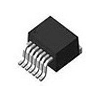
LM4752TS National Semiconductor, LM4752TS Datasheet - Page 15

LM4752TS
Manufacturer Part Number
LM4752TS
Description
IC, AMP, AUDIO, 11W, AB, 7TO263
Manufacturer
National Semiconductor
Datasheet
1.LM4752TS.pdf
(22 pages)
Specifications of LM4752TS
Operational Class
Class-AB
Audio Amplifier Output Configuration
2-Channel Stereo
Output Power (typ)
7x2@8OhmW
Audio Amplifier Function
Speaker
Total Harmonic Distortion
0.08@8Ohm@2W%
Single Supply Voltage (typ)
12/15/18/24/28V
Dual Supply Voltage (typ)
Not RequiredV
Power Supply Requirement
Single
Power Dissipation
62.5W
Rail/rail I/o Type
No
Power Supply Rejection Ratio
50dB
Single Supply Voltage (min)
9V
Single Supply Voltage (max)
32V
Dual Supply Voltage (min)
Not RequiredV
Dual Supply Voltage (max)
Not RequiredV
Operating Temp Range
-40C to 85C
Operating Temperature Classification
Industrial
Mounting
Surface Mount
Pin Count
7 +Tab
Package Type
TO-263
Amplifier Class
AB
No. Of Channels
2
Output Power
11W
Supply Voltage Range
9V To 32V
Thd + N
0.08% @ 1W, 8ohm, VCC=24V
Load Impedance
4ohm
Operating Temperature Range
-40°C To +85°C
Rohs Compliant
Yes
Amplifier Case Style
TO-263
Lead Free Status / RoHS Status
Not Compliant
Available stocks
Company
Part Number
Manufacturer
Quantity
Price
Part Number:
LM4752TS
Manufacturer:
NS/国半
Quantity:
20 000
PREVENTING OSCILLATIONS
With the integration of the feedback and bias resistors on-
chip, the LM4752 fits into a very compact package. However,
due to the close proximity of the non-inverting input pins to
the corresponding output pins, the inputs should be AC ter-
minated at all times. If the inputs are left floating, the amplifier
will have a positive feedback path through high impedance
coupling, resulting in a high frequency oscillation. In most ap-
plications, this termination is typically provided by the previ-
ous stage's source impedance. If the application will require
an external signal, the inputs should be terminated to ground
with a resistance of 50 kΩ or less on the AC side of the input
coupling capacitors.
FIGURE 6. THD+N vs. P
FIGURE 5. Bridge-Mode Application
10003931
OUT
15
for Bridge-Mode Application
UNDERVOLTAGE SHUTDOWN
If the power supply voltage drops below the minimum oper-
ating supply voltage, the internal under-voltage detection cir-
cuitry pulls down the half-supply bias line, shutting down the
preamp section of the LM4752. Due to the wide operating
supply range of the LM4752, the threshold is set to just under
9V. There may be certain applications where a higher thresh-
old voltage is desired. One example is a design requiring a
high operating supply voltage, with large supply and bias ca-
pacitors, and there is little or no other circuitry connected to
the main power supply rail. In this circuit, when the power is
disconnected, the supply and bias capacitors will discharge
at a slower rate, possibly resulting in audible output distortion
as the decaying voltage begins to clip the output signal. An
10003930
10003937
www.national.com


