PX1004 RFM, PX1004 Datasheet
PX1004
Specifications of PX1004
Available stocks


Related parts for PX1004


PX1004 Summary of contents
Page 1
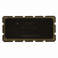
... MHz SAW Filter Units dBm VDC °C SM13365-12 Min Typ 82.200 1 3 ±15 ± 2 -20 External L-C SM13365-12 13.3 X 6.5 mm Nominal Footprint RFM PX1004 YYWW Max Units MHz 4.0 dB kHz dB 1.0 P-P µs 6.0 P-P -95 dBm dB °C +70 Page PX1004 - 2/11/09 ...
Page 2
... E-mail: info@rfm.com ©2009 by RF Monolithics, Inc. Page PX1004 - 2/11/09 ...
Page 3
... E-mail: info@rfm.com ©2009 by RF Monolithics, Inc. Page PX1004 - 2/11/09 ...
Page 4
... See Detail "A" www.RFM.com E-mail: info@rfm.com ©2009 by RF Monolithics, Inc. 12.0 24.4 21.0 2.0 COMPONENT ORIENTATION and DIMENSIONS Carrier Tape Dimensions PIN #1 Quantity Per Reel 100 Min 1000 Max Pitch W USER DIRECTION OF FEED 7.0 mm 13.8 mm 2.0 mm 12.0 mm 24.0 mm Page PX1004 - 2/11/09 ...
Page 5
... TOP VIEW Case Dimensions mm Min Nom Max Min 13.08 13.31 13.60 0.515 6.27 6.50 6.80 0.247 1.91 2.00 1.50 0.79 1.0 2. BOTTOM VIEW Inches Nom Max 0.524 0.535 0.256 0.268 0.075 0.079 0.059 0.031 0.039 0.100 Places (10 Places Page PX1004 - 2/11/09 ...