S-35390A-J8T1G Seiko Instruments, S-35390A-J8T1G Datasheet - Page 13

S-35390A-J8T1G
Manufacturer Part Number
S-35390A-J8T1G
Description
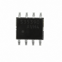
IC RTC I2C 2-WIRE 8-SOP
Manufacturer
Seiko Instruments
Type
Clock/Calendarr
Datasheet
1.S-35390A-J8T1G.pdf
(56 pages)
Specifications of S-35390A-J8T1G
Time Format
HH:MM:SS (12/24 hr)
Date Format
YY-MM-DD-dd
Interface
I²C, 2-Wire Serial
Voltage - Supply
1.3 V ~ 5.5 V
Operating Temperature
-40°C ~ 85°C
Mounting Type
Surface Mount
Package / Case
8-SOP
Lead Free Status / RoHS Status
Lead free / RoHS Compliant
Memory Size
-
Other names
728-1006-2
Available stocks
Company
Part Number
Manufacturer
Quantity
Price
Part Number:
S-35390A-J8T1G
Manufacturer:
SEIKO/精工
Quantity:
20 000
Rev.3.0
3. Status register 2
B0 : TEST
B1 : INT2AE, B2 : INT2ME, B3 : INT2FE
B4 : 32kE, B5 : INT1AE, B6 : INT1ME, B7 : INT1FE
Status register 2 is a 1-byte register that is used to display and set various modes. The bit configuration is shown below.
*1. Don’t care (Both of 0 and 1 are acceptable).
*1. Don’t care (Both of 0 and 1 are acceptable).
This is a test flag for SII. Be sure to set this flag to “0” in use. If this flag is set to “1”, be sure to initialize to set “0”.
These bits are used to select the output mode for the
alarm 2 interrupt, set alarm interrupt mode, then access the INT2 register.
These bits are used to select the output mode for the
alarm 1 interrupt, access the INT1 register after setting the alarm interrupt mode.
INT2AE
_00
32kE
−
−
−
INT1FE
0
1
0
0
0
0
0
0
1
*1
*1
*1
R/W
B7
INT1ME
INT2ME
INT1AE
R/W
B6
−
−
−
0
0
1
1
0
0
0
1
1
*1
*1
*1
INT1AE
R/W
B5
Table 10 Output Modes for
Table 11 Output Modes for
INT1ME
INT2FE
−
0
0
1
1
0
1
*1
Figure 13 Status Register 2
0
1
0
1
0
Seiko Instruments Inc.
32kE
R/W
B4
INT1FE
No interrupt
Output of user-set frequency
Per-minute edge interrupt
Minute-periodical interrupt 1 (50% duty)
Alarm 2 interrupt
−
0
1
0
1
0
1
*1
INT2FE
INT
R/W
INT
B3
2
1
pin. Table 10 shows how to select the mode. To use an
No interrupt
Output of user-set frequency
Per-minute edge interrupt
Minute-periodical interrupt 1 (50% duty)
Alarm 1 interrupt
Minute-periodical interrupt 2
32.768 kHz output
pin. Table 11 shows how to select the mode. To use
INT
INT
R/W: Read/Write
INT2ME
R/W
1
2
B2
INT
Pin
Pin
2
INT
Pin Output Mode
2-WIRE REAL-TIME CLOCK
INT2AE
1
R/W
B1
Pin Output Mode
TEST
R/W
B0
S-35390A
13


