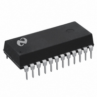
DP8573AN National Semiconductor, DP8573AN Datasheet

DP8573AN
Specifications of DP8573AN
8573
Available stocks
Related parts for DP8573AN
DP8573AN Summary of contents
Page 1
... P interface The time power fails may be logged into RAM automatically when V V Additionally two supply pins are provided When V CC Block Diagram TRI-STATE is a registered trademark of National Semiconductor Corporation C 1995 National Semiconductor Corporation TL F 9981 V internal circuitry will automatically switch from the l ...
Page 2
... Absolute Maximum Ratings If Military Aerospace specified devices are required please contact the National Semiconductor Sales Office Distributors for availability and specifications Supply Voltage ( Input Voltage ( Output Voltage ( OUT Storage Temperature Range Power Dissipation (PD) Lead Temperature (Soldering 10 sec ) DC Electrical Characteristics PFAIL l ...
Page 3
AC Electrical Characteristics PFAIL Symbol READ TIMING t Address Valid Prior to Read Strobe AR t Read Strobe Width (Note Chip Select to Data Valid ...
Page 4
Timing Waveforms Pin Description (Inputs) These pins interface to lines The CS pin is an active low enable for the read and write operations Read and Write pins are also active low and enable reading or writing ...
Page 5
... Connection Diagrams Dual-In-Line Top View Order Number DP8573AN See NS Package Number N24C Functional Description The DP8573A contains a fast access real time clock inter- rupt control logic and power fail detect logic All functions of the RTC are controlled by a set of seven registers A simpli- ...
Page 6
Functional Description (Continued) READING THE CLOCK VALIDATED READ Since clocking of the counter occurs asynchronously to reading of the counter it is possible to read the counter while it is being incremented (rollover) This may result in an incorrect time ...
Page 7
Functional Description (Continued) XTAL 768 kHz pF–22 pF 150 k INTERRUPT LOGIC FUNCTIONAL DESCRIPTION The RTC has the ability to coordinate processor timing ac- tivities To enhance this an interrupt structure has ...
Page 8
Functional Description (Continued) 8 ...
Page 9
Functional Description (Continued) POWER FAIL INTERRUPTS DESCRIPTION The Power Fail Status Flag in the Main Status Register monitors the state of the internal power fail signal This flag may be interrogated by the P but it cannot be cleared it ...
Page 10
Functional Description (Continued) ternal interrupt will be issued Note that the linear power fail circuitry is switched off automatically when using V standby mode INITIAL POWER ON DETECT AND POWER FAIL TIME SAVE There are two other functions provided on ...
Page 11
Functional Description (Continued) MAIN STATUS REGISTER The Main Status Register is always located at address 0 regardless of the register block selected D0 This read only bit is a general interrupt status bit that is taken directly from the interrupt ...
Page 12
Functional Description (Continued) D0 –D1 These are the leap year counter bits These bits are written to set the number of years from the previous leap year The leap year counter increments on December 31st and it internally enables the ...
Page 13
Control and Status Register Address Bit Map Main Status Register ADDRESS Register RAM RAM Select Periodic Flag Register ...
Page 14
Application Hints (Continued) 5 Test bit D6 in the Periodic Flag Register this bit remains a 1 after 3 seconds then abort and check hardware The crystal may be de- fective or ...
Page 15
... TL F 9981– 20 Physical Dimensions inches (millimeters) Operating Current vs Supply Voltage (Battery Backed Mode F 32 768 kHz) e OSC TL F 9981– 21 Molded Dual-In-Line Package (N) Order Number DP8573AN NS Package Number N24C 15 Standby Current vs Power Supply Voltage (F 32 768 kHz) e OSC TL F 9981 – 22 ...
Page 16
... National Semiconductor National Semiconductor National Semiconductores Japan Ltd Hong Kong Ltd Do Brazil Ltda Sumitomo Chemical 13th Floor Straight Block ...


