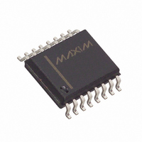
DS1267S-100 Maxim Integrated Products, DS1267S-100 Datasheet - Page 5

DS1267S-100
Manufacturer Part Number
DS1267S-100
Description
IC POT DUAL DIGITAL 100K 16-SOIC
Manufacturer
Maxim Integrated Products
Datasheet
1.DS1267-100.pdf
(12 pages)
Specifications of DS1267S-100
Taps
256
Resistance (ohms)
100K
Number Of Circuits
2
Temperature Coefficient
750 ppm/°C Typical
Memory Type
Volatile
Interface
3-Wire Serial
Voltage - Supply
4.5 V ~ 5.5 V
Operating Temperature
-40°C ~ 85°C
Mounting Type
Surface Mount
Package / Case
16-SOIC (0.300", 7.5mm Width)
Resistance In Ohms
100K
Lead Free Status / RoHS Status
Contains lead / RoHS non-compliant
Other names
DS1267S100
Available stocks
Company
Part Number
Manufacturer
Quantity
Price
Company:
Part Number:
DS1267S-100
Manufacturer:
DALLAS
Quantity:
4 218
Company:
Part Number:
DS1267S-100
Manufacturer:
DALLAS
Quantity:
1 459
Part Number:
DS1267S-100
Manufacturer:
MAXIM/美信
Quantity:
20 000
Company:
Part Number:
DS1267S-100+
Manufacturer:
Maxim
Quantity:
565
Company:
Part Number:
DS1267S-100+
Manufacturer:
Maxim
Quantity:
13 725
The C
multiple devices, the total number of bits transmitted is always 17 times the number of DS1267s in the
daisy chain.
An optional feedback resistor can be placed between the C
DS1267 DQ input, thus allowing the controlling processor to read as well as write data or circularly clock
data through the daisy chain. The value of the feedback or isolation resistor should be in the range from 1
to 10 kohms.
When reading data via the C
device. When
pin through the isolation resistor. When the CLK input transitions low to high, bit 17 is loaded into the
first position of the I/O shift register and bit 16 becomes present on C
17 bits (or 17 times the number of DS1267s in the daisy chain), the data has shifted completely around
and back to its original position. When
same as before the read occurred) is loaded into the wiper-0, wiper-1, and stack select bit I/O register.
ABSOLUTE AND RELATIVE LINEARITY
Absolute linearity is defined as the difference between the actual measured output voltage and the
expected output voltage. Figure 5 presents the test circuit used to measure absolute linearity. Absolute
linearity is given in terms of a minimum increment or expected output when the wiper is moved one
position. In the case of the test circuit, a minimum increment (MI) or one LSB would equal 10/512 volts.
The equation for absolute linearity is given as follows:
(1)
Relative Linearity is a measure of error between two adjacent wiper position points and is given in terms
of MI by equation (2).
(2)
Figure 6 is a plot of absolute linearity and relative linearity versus wiper position for the DS1267 at 25°C.
The specification for absolute linearity of the DS1267 is ±0.75 MI typical. The specification for relative
linearity of the DS1267 is ±0.3 MI typical.
OUT
ABSOLUTE LINEARITY
AL={V
RELATIVE LINEARITY
RL={V
output of the DS1267 can be used to drive the DQ input of another DS1267. When connecting
O
O
RST
(actual) - V
(n+1) - V
is driven high, bit 17 is present on the C
O
(n)}/MI
O
OUT
(expected)}/MI
pin and isolation resistor, the DQ line is left floating by the reading
RST
transitions to the low state to end data transfer, the value (the
5 of 12
OUT
OUT
terminal of the last device and the first
pin, which is fed back to the input DQ
OUT
and DQ of the next device. After
102199
DS1267


