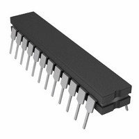
AD7837AQ Analog Devices Inc, AD7837AQ Datasheet

AD7837AQ
Specifications of AD7837AQ
Related parts for AD7837AQ
AD7837AQ Summary of contents
Page 1
...
Page 2
AD7837/AD7847–SPECIFICATIONS = + 100 pF [V REFA REFB L L Parameter A Version STATIC PERFORMANCE Resolution 12 ± Relative Accuracy ± Differential ...
Page 3
... Model AD7837AN – 0 0.3 V AD7837BN DD + 0.3 V AD7837AR DD AD7837BR – 0 0.3 V AD7837AQ DD AD7837BQ – 0 0.3 V AD7837SQ AD7847AN AD7847BN AD7847AR AD7847BR AD7847AQ AD7847BQ AD7847SQ NOTES 1 To order MIL-STD-883, Class B processed parts, add /883B to part number. pin will float ...
Page 4
AD7837/AD7847 TERMINOLOGY Relative Accuracy (Linearity) Relative accuracy, or endpoint linearity measure of the maximum deviation of the DAC transfer function from a straight line passing through the endpoints measured after allowing for zero and full-scale errors ...
Page 5
AD7847 PIN FUNCTION DESCRIPTION (DIP AND SOIC PIN NUMBERS) Pin Mnemonic Description CSA 11 Chip Select Input for DAC A. Active low logic input. DAC A is selected when this input is low. CSB 12 Chip Select Input for DAC ...
Page 6
AD7837/AD7847–Typical Performance Graphs 10 0 – +15V –15V +20Vp–p REF –20 DAC CODE = 111...111 – FREQUENCY – Hz 0.5 0 7.5V ...
Page 7
CIRCUIT INFORMATION D/A SECTION A simplified circuit diagram for one of the D/A converters and output amplifier is shown in Figure 10. A segmented scheme is used whereby the 2 MSBs of the 12-bit data word are decoded to drive ...
Page 8
AD7837/AD7847 A0/A1 ADDRESS DATA VALID DATA DATA LDAC CS, WR, A0 and A1 control the loading of data to the input latches. The eight ...
Page 9
BIPOLAR OPERATION (4-QUADRANT MULTIPLICATION) Figure 16 shows the AD7837/AD7847 connected for bipolar operation. The coding is offset binary as shown in Table IV. When signal, the circuit performs 4-quadrant multi- IN plication. To maintain the gain ...
Page 10
AD7837/AD7847 ANALOG PANNING CIRCUIT In audio applications it is often necessary to digitally “pan” or split a single signal source into a two-channel signal while main- taining the total power delivered to both channels constant. This may be done very ...
Page 11
ADDRESS BUS 8086 ADDRESS 16 BIT DECODE ALE LATCH WR AD15 ADDRESS/DATA BUS AD0 ADDITIONAL PINS OMITTED FOR CLARITY AD7847–MC68000 Interface Figure 21 shows an interface between the AD7847 and the MC68000. Once again a single MOVE instruction loads the ...
Page 12
AD7837/AD7847 AD7837–6502/6809 Interface Figure 25 shows an interface between the AD7837 and the 6502 or 6809 microprocessor. For the 6502 microprocessor, the φ2 clock is used to generate the WR, while for the 6809 the E sig- nal is used. ...


