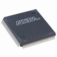
EPF10K100EQI208-2 Altera, EPF10K100EQI208-2 Datasheet - Page 24

EPF10K100EQI208-2
Manufacturer Part Number
EPF10K100EQI208-2
Description
IC FLEX 10K FPGA 100K 208-PQFP
Manufacturer
Altera
Series
FLEX-10KE®r
Datasheet
1.EPF10K30ETC144-3.pdf
(100 pages)
Specifications of EPF10K100EQI208-2
Number Of Logic Elements/cells
4992
Number Of Labs/clbs
624
Total Ram Bits
49152
Number Of I /o
147
Number Of Gates
257000
Voltage - Supply
2.375 V ~ 2.625 V
Mounting Type
Surface Mount
Operating Temperature
-40°C ~ 100°C
Package / Case
208-MQFP, 208-PQFP
Lead Free Status / RoHS Status
Contains lead / RoHS non-compliant
Available stocks
Company
Part Number
Manufacturer
Quantity
Price
Company:
Part Number:
EPF10K100EQI208-2
Manufacturer:
MAXIM
Quantity:
1 001
Company:
Part Number:
EPF10K100EQI208-2N
Manufacturer:
SANEKN
Quantity:
6 000
FLEX 10KE Embedded Programmable Logic Devices Data Sheet
24
Clearable Counter Mode
The clearable counter mode is similar to the up/down counter mode, but
supports a synchronous clear instead of the up/down control. The clear
function is substituted for the cascade-in signal in the up/down counter
mode. Use 2 three-input LUTs: one generates the counter data, and the
other generates the fast carry bit. Synchronous loading is provided by a
2-to-1 multiplexer. The output of this multiplexer is AND ed with a
synchronous clear signal.
Internal Tri-State Emulation
Internal tri-state emulation provides internal tri-states without the
limitations of a physical tri-state bus. In a physical tri-state bus, the
tri-state buffers’ output enable (OE) signals select which signal drives the
bus. However, if multiple OE signals are active, contending signals can be
driven onto the bus. Conversely, if no OE signals are active, the bus will
float. Internal tri-state emulation resolves contending tri-state buffers to a
low value and floating buses to a high value, thereby eliminating these
problems. The Altera software automatically implements tri-state bus
functionality with a multiplexer.
Clear & Preset Logic Control
Logic for the programmable register’s clear and preset functions is
controlled by the DATA3, LABCTRL1, and LABCTRL2 inputs to the LE. The
clear and preset control structure of the LE asynchronously loads signals
into a register. Either LABCTRL1 or LABCTRL2 can control the
asynchronous clear. Alternatively, the register can be set up so that
LABCTRL1 implements an asynchronous load. The data to be loaded is
driven to DATA3; when LABCTRL1 is asserted, DATA3 is loaded into the
register.
During compilation, the Altera Compiler automatically selects the best
control signal implementation. Because the clear and preset functions are
active-low, the Compiler automatically assigns a logic high to an unused
clear or preset.
The clear and preset logic is implemented in one of the following six
modes chosen during design entry:
Asynchronous clear
Asynchronous preset
Asynchronous clear and preset
Asynchronous load with clear
Asynchronous load with preset
Asynchronous load without clear or preset
Altera Corporation


