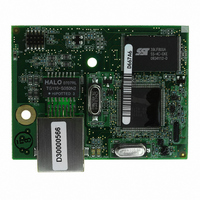
20-101-1215 Rabbit Semiconductor, 20-101-1215 Datasheet - Page 113

20-101-1215
Manufacturer Part Number
20-101-1215
Description
MCU RCM4050 RABBITCORE
Manufacturer
Rabbit Semiconductor
Datasheet
1.20-101-1094.pdf
(130 pages)
Specifications of 20-101-1215
Module/board Type
MPU Core Module
For Use With/related Products
RCM4050
Lead Free Status / RoHS Status
Lead free / RoHS Compliant
Other names
316-1145
- Current page: 113 of 130
- Download datasheet (809Kb)
Many other possible ranges are possible by physically changing the resistor values that
make up the attenuator circuit.
It is also possible to read a negative voltage on LN0_IN–LN5_IN by moving the 0
jumper (see Figure B-6) on header JP23 or JP24 associated with the A/D converter input
from analog ground to the reference voltage generated and buffered by the A/D converter.
Adjacent input channels are paired; moving the jumper on JP 23 changes both of the
paired channels (LN4_IN–LN5_IN), and moving the jumper on JP24 changes LN0_IN–
LN3_IN. At the present time Rabbit does not offer the software drivers to work with single-
ended negative voltages, but the differential mode described below may be used to measure
negative voltages.
Differential measurements require two channels. As the name differential implies, the dif-
ference in voltage between the two adjacent channels is measured rather than the differ-
ence between the input and analog ground. Voltage measurements taken in differential
mode have a resolution of 12 bits, with the 12th bit indicating whether the difference is
positive or negative.
The A/D converter chip can only accept positive voltages, as explained in Section 4.4. Both
differential inputs must be referenced to analog ground, and both inputs must be positive
with respect to analog ground. Table B-4 provides the differential voltage ranges for this
setup.
User’s Manual
Min. Differential
Voltage
NOTE: Analog input LN7_IN does not have the 10 k resistor installed, and so no
(V)
0
0
0
0
0
0
0
0
resistor attenuator is available, limiting its maximum input voltage to 2 V. This input is
intended to be used for a thermistor that you may install at header location JP25.
Max. Differential
Voltage (with
prescaler)
Table B-4. Differential Voltage Ranges
±22.528
±11.264
±5.632
±4.506
±2.816
±2.253
±1.408
±1.126
(V)
Multiplier
Gain
×10
×16
×20
×1
×2
×4
×5
×8
A/D Converter
Actual Gain
14.4
1.8
3.6
4.5
7.2
9.0
18
1
Resolution
(mV)
1.375
1.100
0.688
0.550
2.75
2.20
5.5
11
107
Related parts for 20-101-1215
Image
Part Number
Description
Manufacturer
Datasheet
Request
R

Part Number:
Description:
COMPUTER SGL-BRD BL2500 29.4MHZ
Manufacturer:
Rabbit Semiconductor
Datasheet:

Part Number:
Description:
COMPUTER SGL-BRD BL2500 29.4MHZ
Manufacturer:
Rabbit Semiconductor
Datasheet:

Part Number:
Description:
DISPLAY GRAPHIC 12KEY PROG OP670
Manufacturer:
Rabbit Semiconductor
Datasheet:

Part Number:
Description:
DISPLAY GRAPHIC 12KEY ETH OP6700
Manufacturer:
Rabbit Semiconductor
Datasheet:

Part Number:
Description:
COMPUTER SINGLE-BOARD BL2030
Manufacturer:
Rabbit Semiconductor

Part Number:
Description:
COMPUTER SGL-BOARD ETH BL2010
Manufacturer:
Rabbit Semiconductor

Part Number:
Description:
MODULE OP6810 W/O ETH/MEM EXPANS
Manufacturer:
Rabbit Semiconductor
Datasheet:

Part Number:
Description:
COMPUTER SINGLE-BOARD BL2020
Manufacturer:
Rabbit Semiconductor

Part Number:
Description:
COMPUTER BL2010 W/FRICTION LOCK
Manufacturer:
Rabbit Semiconductor

Part Number:
Description:
COMPUTER BL2020 W/FRICTION LOCK
Manufacturer:
Rabbit Semiconductor

Part Number:
Description:
COMPUTER SGL-BRD BL2500 44.2MHZ
Manufacturer:
Rabbit Semiconductor
Datasheet:

Part Number:
Description:
COMPUTER SGL-BOARD FULL BL2000
Manufacturer:
Rabbit Semiconductor

Part Number:
Description:
COMPUTER SINGLE-BOARD BL2110
Manufacturer:
Rabbit Semiconductor

Part Number:
Description:
COMPUTER SGL-BRD 29.4MHZ BL2610
Manufacturer:
Rabbit Semiconductor
Datasheet:

Part Number:
Description:
INTERFACE OP6800 512K FLASH&SRAM
Manufacturer:
Rabbit Semiconductor
Datasheet:


