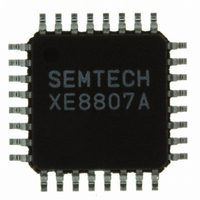
XE8807AMI026TLF Semtech, XE8807AMI026TLF Datasheet - Page 73

XE8807AMI026TLF
Manufacturer Part Number
XE8807AMI026TLF
Description
IC MCU LOW PWR MTP FLASH 32-TQFP
Manufacturer
Semtech
Datasheet
1.XE8807AMI026TLF.pdf
(143 pages)
Specifications of XE8807AMI026TLF
Applications
Sensing Machine
Core Processor
RISC
Program Memory Type
FLASH (11 kB)
Controller Series
XE8000
Ram Size
512 x 8
Interface
UART, USRT
Number Of I /o
24
Voltage - Supply
2.4 V ~ 5.5 V
Operating Temperature
-40°C ~ 85°C
Mounting Type
Surface Mount
Package / Case
32-TQFP, 32-VQFP
For Use With
XE8000MP - PROG BOARD AND PROSTART2 CARD
Lead Free Status / RoHS Status
Lead free / RoHS Compliant
Other names
XE8807AMI026TR
Available stocks
Company
Part Number
Manufacturer
Quantity
Price
Company:
Part Number:
XE8807AMI026TLF
Manufacturer:
IDT
Quantity:
62
Table 12-8 shows the different usages that can be made of port B with the order of priority. If a pin is selected to be
analog, it overwrites the function and digital set-up. If the pin is not selected as analog, but a function is enabled, it
overwrites the digital set-up. If neither the analog nor function is selected for a pin, it is used as an ordinary digital
I/O. This is the default configuration at start-up.
Note: the presence of the functions is product dependent.
12.5 Port B analog capability
12.5.1
Port B terminals can be attached to a 4 line analog bus by setting the PBAna[x] bits to 1 in the RegPBAna
register.
The other registers then define the connection of these 4 analog lines to the different pads of Port B. These can be
used to implement a simple LCD driver or A/D converter. Analog switching is available only when the circuit is
powered with sufficient voltage (see specification below). Below the specified supply voltage, only voltages that are
close to VSS or VBAT can be switched.
When PBAna[x] is set to 1, one pad of the Port B terminals is changed from digital I/O mode to analog. The usage
of the registers RegPBPullup, RegPBOut and RegPBDir define the analog configuration (see Table 12-9).
When PBAna[x] = 1, then PBPullup[x] connects the pin to the analog bus. PBDir[x] and PBPOut[x] select which
of the 4 analog lines is used.
Example:
© Semtech 2006
Table 12-9: Selection of the analog lines with RegPBDir, RegPBout and RegPBPullup when PBAna[x] = 1
Set the pads PB[2] and PB[5] on the analog line 3. (the values X depend on the configuration of others
pads)
-
-
-
-
Port B analog configuration
apply high impedance in the analog mode (move RegPBPullup,#0bXX0XX0XX)
go to analog mode (move RegPBAna,#0bXX1XX1XX)
select the analog line3 (move RegPBDir,#0bXX1XX1XX and move RegPBOut,#0bXX1XX1XX)
apply the analog line to the output (move RegPBPullup,#0bXX1XX1XX)
PBDir[x]
analog bus selection
0
0
1
1
X
PBout[x]
X
0
1
0
1
12-4
PBPullup[x]
1
1
1
1
0
PB[x] selection on
High impedance
analog line 0
analog line 1
analog line 2
analog line 3
XE8806A/XE8807A
www.semtech.com


